Many metal stamping problems do not start in the tool room. They start in the CAD model.
📖 Complete Overview Of Metal Stamping — Read our complete overview of metal stamping to learn more about design for metal stamping.
A part can look neat on a screen and still be a poor stamping design. Holes may sit too close to formed edges. Radii may be tighter than the material can tolerate. Flanges may be too short to form consistently. Tolerances may be written as if every dimension can be held equally well before and after multiple forming stages. None of those issues are unusual. They are exactly what turns a straightforward stamping program into expensive tooling, unstable production, long launch cycles, and repeated engineering correction.
That is why good stamped-part design is not only about shape. It is about designing a geometry that respects how sheet metal behaves under cutting, bending, drawing, restriking, and handling.
If you need process context first, start with our overview of what is metal stamping. If you are already sourcing real components, our metal stamping parts and custom metal stamped parts pages show the kinds of production parts where these design rules matter most.
What Good Stamping Part Design Actually Means
A good metal stamping part design is not simply a part that can be made once.
A good design is one that can be produced:
- with a realistic die concept
- at repeatable quality
- at acceptable scrap levels
- with manageable tool maintenance
- with dimensions that remain stable through the forming sequence
- with a cost structure that still makes sense at the target volume
This distinction matters because many design teams ask the wrong first question.
They ask, “Can this be stamped?”
The better question is, “Can this be stamped economically and repeatedly without building unnecessary risk into the tool and production route?”
That is the frame experienced suppliers use during metal stamping design guidelines reviews.
The First Design Rule: Respect the Process Sequence
A stamped part is not produced all at once. It is created through a sequence.
That means the designer should stop thinking only about the final geometry and start thinking about the order in which the metal must be cut, supported, bent, stretched, restrained, and released.
A hole that looks fine in the final model may distort if it is pierced too early and then dragged through a later forming stage. A flange that looks dimensionally minor may be impossible to form reliably because there is not enough material support around it at the station where it needs to be made.
When engineers ignore process sequence, they often create:
- unnecessary die stations
- unstable carriers in progressive dies
- post-form hole shift
- difficult trim access
- restrictive tooling clearances
- avoidable secondary operations
Good design starts with this assumption: every feature must not only exist on the final part—it must also fit into a manufacturable forming route.
Holes Near Edges: One of the Most Common Design Mistakes
Hole placement is one of the fastest ways to tell whether a part was designed with stamping in mind.
If a hole is placed too close to a cut edge, bend line, draw wall, or narrow bridge of material, several problems can appear:
- edge breakout during piercing
- local distortion during forming
- burr sensitivity
- tear risk under load
- loss of positional accuracy after bending
A drawing may not show any of those issues. The tool will.
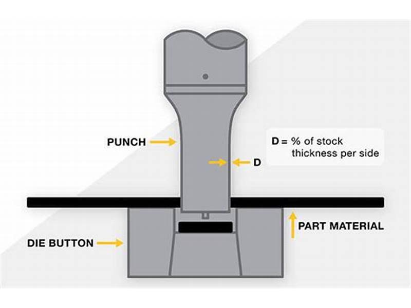
Practical Design Logic for Hole Placement
As a rule, holes need enough surrounding material to survive both piercing and later deformation. The correct distance depends on material thickness, hole size, material grade, nearby forming, and tolerance demands. There is no single universal number that fits every program.
But the practical principle is clear: the closer the hole is to an edge or forming transition, the more likely it becomes that the hole will either distort or force the tool designer into more complicated process control.
This matters even more on higher-accuracy programs. If the part is headed for precision metal stamping, the design should make it easier—not harder—to maintain feature location after processing.
Radii: Tight Corners Look Clean in CAD and Cost Real Money in Production
Sharp internal geometry is one of the most common ways designers unknowingly raise tooling and process risk.
In sheet metal stamping, radii are not cosmetic. They affect:
- material flow
- crack risk
- springback behavior
- tool wear
- edge quality
- repeatability after release from the die
If an inside bend radius is too tight for the selected thickness and material condition, the outer fibers of the metal may stretch beyond what the alloy can tolerate. That can lead to surface fracture, thinning, or unstable dimensional recovery.
Why Reasonable Radii Help More Than Just Forming
Larger or more practical radii can improve far more than crack resistance. They also reduce:
- the need for aggressive restrike operations
- angle variation from springback
- stress concentration in service
- die maintenance burden
- time spent tuning first articles
This is especially relevant for parts with multiple bends or formed transitions. One unrealistic radius does not stay isolated. It affects the whole die route.
Bend Relief and Corner Treatment
A surprising number of stamped-part drawings overlook bend relief altogether.
When a flange is bent near a side edge or another intersecting feature, the material needs space to deform. Without proper relief, the corner zone can tear, buckle, or pull in a way that changes the final shape.
Designers often discover this too late, after the tool concept is already priced.
Why Bend Relief Matters
Proper relief helps the material transition through the bend instead of fighting itself at the corner. It can improve:
- flange consistency
- corner quality
- dimensional stability
- cosmetic appearance
- tool robustness during long runs
Relief geometry does not need to be excessive. It just needs to be deliberate.
Ignoring it usually means the tool has to compensate for a design problem that should have been solved in the drawing.
Flange Height: Short Flanges Are Often Harder Than Buyers Expect
A flange may look simple, but in stamping it is only as reliable as the material support behind it.
Very short flanges are often difficult because:
- there is limited forming leverage
- the bend zone is crowded
- springback becomes more influential relative to feature size
- tool contact area is small
- adjacent features may interfere with punch or die access
This does not mean short flanges are impossible. It means they should not be treated casually.
If a flange is functionally necessary, the design team should ask:
- Does the flange need to be that short?
- Can the part datum scheme tolerate some formed variation?
- Would a different geometry reduce tool complexity?
- Is a secondary operation being forced by the current layout?
The same logic applies to narrow return bends, offset forms, and closely spaced formed walls.
Embosses, Extrusions, and Local Forms
Embosses and extruded features are useful because they add function without requiring separate parts. They can create stiffness, stand-off height, identification, thread engagement, or localized positioning.
But these features are often designed as if they exist independently of surrounding geometry. They do not.
Their manufacturability depends on:
- material thickness
- feature height relative to thickness
- wall shape and draft
- distance from edges or holes
- nearby bends
- direction of later forming operations
Typical Design Failure Pattern
A designer adds an extrusion or emboss to improve function, then later adds a bend close to it, then later adds a tight hole tolerance through that same local area. Each change looks reasonable in isolation. Together they create a die sequence problem.
The result is usually one of three things:
- the feature has to be made shallower than intended,
- the tool needs more stations and more cost, or
- the part launches with a quality window narrower than the quote assumed.
If the feature truly adds value, that is fine. But it should be treated as a manufacturing decision, not only a geometric decision.
Tolerance Realism: Not Every Dimension Should Be Held the Same Way
One of the biggest cost drivers in stamped-part design is tolerance language that ignores process behavior.
On many drawings, all dimensions are written with equal confidence—as if flat pierced geometry, formed flange angles, post-draw hole locations, and free-state overall length all respond to manufacturing in the same way.
They do not.
Dimensions That Are Naturally Easier to Control
These are usually more stable:
- hole-to-hole distances pierced in the same station
- flat blank profile features before heavy forming
- datums created directly from die-controlled cut geometry
Dimensions That Often Require More Caution
These are usually more process-sensitive:
- hole location after bending or drawing
- angle and form dimensions influenced by springback
- flange-to-flange relationships across multiple bends
- large formed envelopes measured in free state
- cosmetic flatness after residual stress release
When drawings assign unnecessarily tight tolerances to highly form-sensitive dimensions, suppliers typically respond in one of four ways:
- increase tooling complexity
- add restrike operations
- slow production control and inspection
- price defensively
- or reject the risk entirely
A practical stamping drawing separates truly critical features from dimensions that only need commercial, not laboratory, precision.
Material Choice Is a Design Decision, Not a Procurement Detail
Material selection is often pushed late in the project, but for stamped parts it belongs much earlier.
Different materials change the whole production behavior:
- low-carbon steel is often forgiving
- stainless steel pushes springback and forming force upward
- aluminum may form well but can be sensitive to galling or surface marking
- higher-strength grades may hold function but resist shaping
- plated or pre-finished stock can raise handling and cosmetic constraints
This means material and geometry must be evaluated together.
A radius that works in mild steel may become risky in stainless. A flange height that is fine at one thickness may become unstable at another. A hole-to-edge rule that looks safe in one alloy can become marginal in a harder temper.
Designers who treat material as a late substitution variable often create hidden tooling revisions.
Part Symmetry, Carrier Logic, and Strip Yield
Not every stamped part will run in a progressive die, but many do. When that is the case, strip logic becomes part of design quality.
Features that affect strip efficiency include:
- overall blank orientation
- mirrored or asymmetrical geometry
- carrier attachment opportunities
- spacing between repeated profiles
- station progression requirements
- part release direction
A part may be fully manufacturable and still waste significant material if the blank layout is inefficient. That waste does not show up in the CAD model. It shows up in scrap percentage and quote price.
This is one reason experienced buyers review more than part geometry. They also ask what the strip layout or die route will probably look like.
Design Choices That Quietly Increase Die Complexity
Some features are not impossible. They are simply expensive in ways the drawing does not make obvious.
Examples include:
- multiple tight-tolerance holes near formed walls
- tiny tabs or bridges that weaken the strip
- mixed-direction forms crowded into one area
- long narrow slots in high-strength material
- aggressive cosmetic requirements on heavily formed surfaces
- post-form dimensions controlled from unstable datums
- unnecessary feature variation from left to right on otherwise similar parts
Each one may seem minor. Together, they can turn a simple stamping tool into a more fragile, slower-launching, higher-maintenance program.
That is why design review should focus not only on feasibility, but on what each feature forces the die to do.
How Bad Design Drives Scrap, Rework, and Slow Launches
Poor stamped-part design does not only increase quoted cost. It creates operational drag after the PO is placed.
Higher Scrap
Material may crack, distort, mark, or fail dimensional checks more often because the part has too little tolerance for natural process movement.
More Rework and Engineering Loops
The supplier may need to request drawing changes, modify tool details, add restrike control, or negotiate tolerance exceptions after first articles.
Longer Tool Build and Debug Time
The die may require more stations, more adjustments, and more tuning before the process stabilizes.
More Secondary Operations
Features that could have been designed into a cleaner stamping route may get pushed into separate trimming, drilling, deburring, or hand correction steps.
None of this is theoretical. This is how launch schedules slip in real programs.
Questions Designers and Buyers Should Ask Before Releasing a Part
Before finalizing a stamped-part drawing, useful questions include:
- Which features are truly critical, and which are only nice to control tightly?
- Are any holes too close to edges, bends, or draw transitions?
- Are any radii tighter than the selected material and thickness can realistically tolerate?
- Do short flanges or local forms create difficult tooling access?
- Will embosses, extrusions, or pierces be affected by later forming?
- Does the material choice still support the geometry as designed?
- Are any tolerances written on dimensions that are naturally form-sensitive?
- Is the design likely to force extra stations or secondary operations?
These questions help catch the expensive issues while they are still cheap to fix.
Final Takeaway
The best metal stamping part designs are not the ones with the most features. They are the ones that convert function into geometry without forcing unnecessary process pain.
A drawing that respects hole placement, radii, bend relief, flange logic, material behavior, and tolerance realism will usually launch faster, quote more competitively, and run more predictably over time.
That is the real goal.
For engineering teams, good stamped-part design means thinking beyond the finished CAD model. For sourcing teams, it means understanding that geometry decisions drive tooling strategy, scrap exposure, inspection burden, and long-term cost.
If the part is being designed for commercial production, those are not side issues. They are the program.
FAQ
What is the most important rule in metal stamping part design?
The most important rule is to design the part around how sheet metal will actually be cut and formed, not only around the final CAD shape. A part should be manufacturable through a stable process sequence with realistic tolerances, practical radii, and features placed where the material can support them.
Why are holes near bends or edges risky in stamped parts?
Holes near bends or edges can distort during forming, break out at the edge, or become harder to hold position accurately. The risk increases when the surrounding material is limited or when later forming changes local shape.
How do tight radii affect stamping cost?
Very tight radii can increase crack risk, springback control difficulty, tool wear, and restrike requirements. Even when they are technically possible, they often raise die complexity and process tuning cost.
Why do stamped-part tolerances need to be realistic?
Different features respond differently to stamping. Flat pierced dimensions are usually easier to control than post-form geometry. If a drawing gives equally tight tolerances to all features, the supplier may need more tooling, more inspection, or more conservative pricing.
Does material choice change how a stamped part should be designed?
Yes. Material affects formability, springback, tool wear, surface sensitivity, and crack risk. A geometry that works well in low-carbon steel may not behave the same way in stainless steel or harder tempers.
Choose a trusted metal stamping manufacturer for your supply chain. We offer custom metal stamping with full quality control.
Frequently Asked Questions
What is metal stamping parts design?
Metal stamping parts design is a specialized manufacturing process used to create precise metal components. Our team has over 25 years of experience delivering high-quality results for global clients across automotive, aerospace, electronics, and construction industries.
What tolerances can you achieve for metal stamping parts design?
We achieve standard tolerances of ±0.05mm, with precision tolerances down to ±0.02mm for critical applications. All parts are inspected using CMM equipment with Cpk≥1.33 process capability.
What materials do you work with for metal stamping parts design?
We work with a wide range of materials including aluminum (1100-6061), stainless steel (301-430), carbon steel, copper, brass, phosphor bronze, and specialty alloys. Material thickness ranges from 0.1mm to 12mm.
What is your minimum order quantity for metal stamping parts design?
We accept prototype orders starting from 1 piece. For production runs, we recommend starting at 1,000 pieces for cost efficiency, though we accommodate various volumes based on project requirements.
How do I get a quote for metal stamping parts design?
Submit your drawings (DWG, DXF, STEP, IGES, or PDF) via our contact form or email. We provide DFM feedback and pricing within 24 hours. Our engineering team reviews every inquiry for optimal manufacturability.
What quality certifications do you have for metal stamping parts design?
We maintain ISO 9001:2015 and IATF 16949 certifications with full traceability. Every shipment includes inspection reports, material certificates, and compliance documentation as required.