Client: Mid-sized European Tier 2 Automotive Supplier
Industry: Automotive Structural Brackets
Project Scope: Progressive Die Design, Manufacturing & Mass Production
Partner: metalstampingparts.ltd — Precision Metal Stamping Manufacturer, China
1. Client Background
Our client, a well-established Tier 2 supplier serving a major European automotive OEM, produces steel reinforcement brackets used in front subframe assemblies. The part — a 2.8 mm-thick cold-rolled steel bracket (SAPH440 grade) measuring approximately 120 mm × 85 mm — is safety-critical, requiring consistent mechanical performance across high-volume production.
At the time of engagement, the client’s annual demand stood at 2,000,000 pieces, with model lifecycle projections extending to 7 years. Their existing manufacturing process relied on a four-station single-operation tooling setup: blanking, piercing, forming, and tapping each executed on separate mechanical presses. This fragmented workflow required four machine operators, four press setups, and significant work-in-progress (WIP) inventory between stations. Per-piece cost had plateaued at $1.82, a figure the client’s procurement team deemed unsustainable given mounting cost-down pressure from their OEM customer.
The client approached us with a clear brief: reduce unit cost below $1.20 while simultaneously doubling monthly throughput from 80,000 to 160,000 pieces — all without compromising the stringent ±0.05 mm dimensional tolerances required for automated robotic welding at the OEM’s assembly line.
2. The Challenge
Three interconnected constraints defined the technical difficulty of this project:
Cost Target. The existing unit cost of $1.82 needed to fall by at least 34%. At 2 million annual units, this represented savings exceeding $1.2 million over a single model year — a non-trivial ask for a mature stamped part already optimized through years of incremental kaizen activities.
Capacity Bottleneck. The single-operation line maximumed out at 80,000 pieces per month across three shifts. Demand projections required 160,000 pieces/month within 18 months. Simply duplicating the existing tooling would have required $240,000 in additional hard tooling investment plus factory floor space the client did not have.
Tolerance Stack-up. With four separate fixtures and four operator-dependent loading/unloading cycles, the process inherently accumulated positioning errors. Maintaining ±0.05 mm on critical hole-to-edge dimensions required 100% in-line inspection and frequent tool adjustments, driving up labor and scrap costs. Any new solution had to eliminate these multi-setup error sources.
The client also carried a 4.7% internal scrap rate, largely attributed to misalignment in the secondary forming and tapping stations.
3. Our Solution
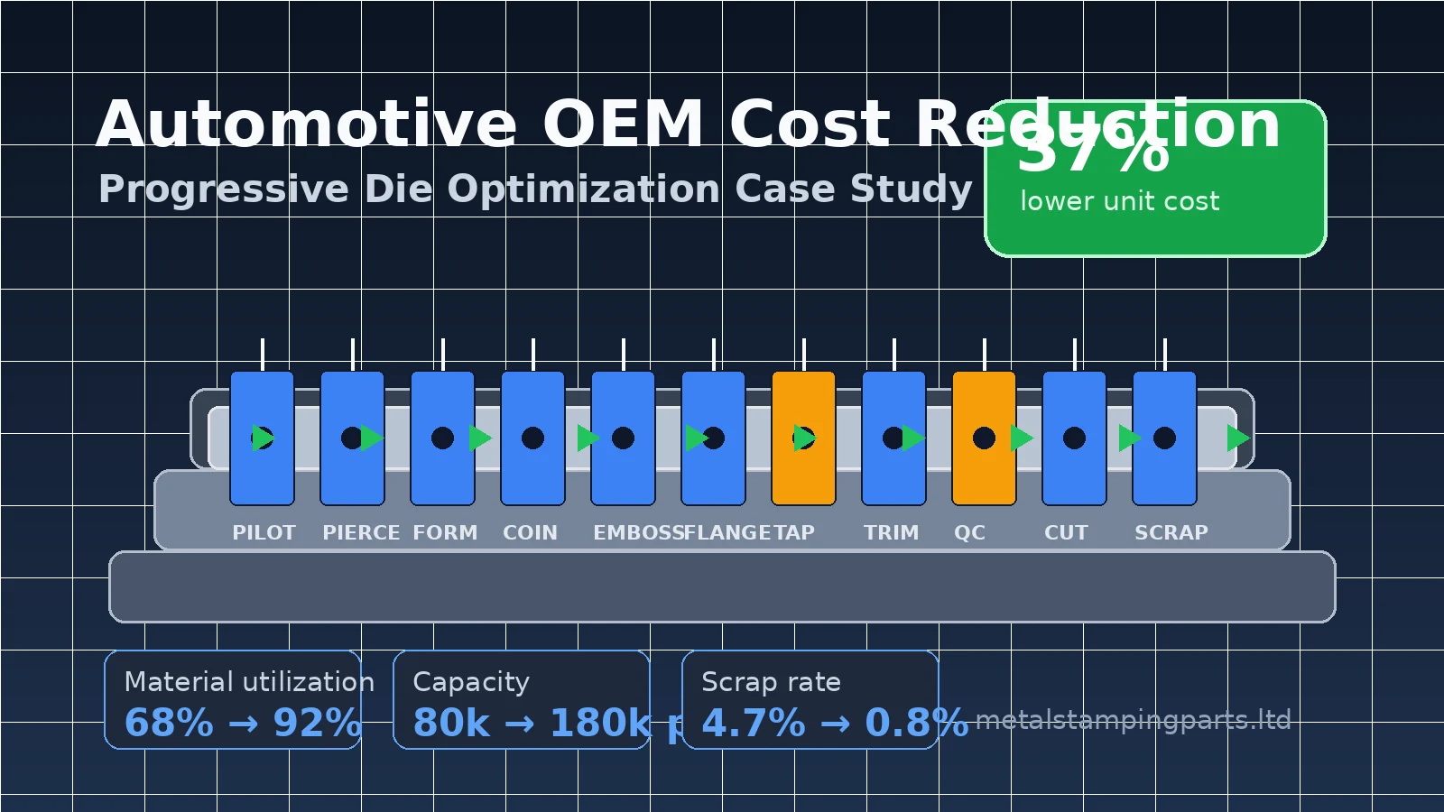
After conducting a detailed Design for Manufacturability (DFM) review with the client’s engineering team, we proposed a single 18-station progressive die consolidating all operations into one continuous press cycle.
3.1 Strip Layout & Material Utilization
The single greatest cost lever was raw material. The original process used a 140 mm-wide coil strip with a single-row layout, yielding 68% material utilization. Our engineering team used AutoForm-based forming simulation to validate a 3-row staggered (zigzag) layout with carrier strip optimization. The new layout narrowed the strip to 108 mm per row in a triple-row configuration, achieving 92% material utilization — a 24-percentage-point gain that alone contributed approximately $0.28 in per-piece material savings.
The 18-station sequence was designed as follows:
| Station | Operation |
| 1 | Pilot hole punching (Ø6.0 mm, 2×) |
|---|---|
| 2–3 | Progressive notching & perimeter roughing |
| 4 | Idle (die structural reinforcement zone) |
| 5–6 | Inner window piercing (oblong slots, 12×5 mm) |
| 7 | Pre-forming bend (45° partial flange) |
| 8 | Idle |
| 9 | Final forming bend (90° ±0.5°) |
| 10 | Restrike / coining for bend radius control |
| 11 | Embossing (stiffening bead, 1.2 mm height) |
| 12–13 | Flanging (Z-bend, both sides simultaneously) |
| 14 | Idle (sensor check zone) |
| 15 | Precision hole piercing (Ø8.2 mm ±0.02 mm, 4×) |
| 16 | Tapping — integrated in-die servo tapping unit (M6×1.0, 2×) |
| 17 | Parting / cut-off |
| 18 | Scrap chopping |
3.2 Tool Steel & Coating Selection
For the high-wear stations (piercing punches, forming inserts, and the tapping station), we specified SKD11 (JIS G4404) cold-work tool steel hardened to 60–62 HRC, with a TiCN (Titanium Carbonitride) PVD coating applied to all cutting and forming surfaces. This combination delivers a surface hardness exceeding 3,000 HV, extending tool life to an estimated 5 million strokes between major refurbishments — critical for a 2M/year program.
Guide pillars and bushings were specified in SKH51 high-speed steel with ball-cage retainers to ensure guiding accuracy within 0.003 mm across the full press stroke.
3.3 In-Die Tapping Integration
Perhaps the most technically ambitious element was integrating the M6×1.0 tapping operation directly into the progressive die at Station 16. Traditional approaches tap off-line using dedicated machines, adding handling costs and cycle time variability. Our design employed a servo-driven in-die tapping unit synchronized with the press crank angle, achieving 50 strokes per minute tapping speed with automatic chip evacuation. In-die tapping eliminated one full operator position and reduced per-part tapping cost from $0.09 to under $0.02.
3.4 Simulation-Driven Validation
Before cutting steel, we ran:
– Forming simulation (AutoForm R8): Validated thinning < 20%, wrinkle-free forming, springback compensation of 0.8° on the 90° flange
– Structural FEA (ANSYS): Confirmed die stresses below 980 MPa on all critical inserts at 250-ton press load
– Strip progression kinematics: Verified pilot engagement at every station, minimum carrier width of 8.5 mm maintained throughout
Pre-production simulation reduced physical tryout iterations from an industry-typical 5–7 rounds to just 3.
4. Implementation
4.1 Manufacturing Timeline
| Phase | Duration | Key Milestones |
| DFM & Strip Layout | Week 1–2 | Simulation-validated layout signed off |
|---|---|---|
| Die Design (3D CAD) | Week 2–4 | Full SolidWorks assembly with 478 components |
| Raw Material Procurement | Week 2–3 | SKD11 blocks sourced from Hitachi Metals |
| CNC Machining & Wire EDM | Week 4–7 | 5-axis machining + Sodick wire EDM for punch/die clearances (6–8% of material thickness) |
| Assembly & Bench Fitting | Week 7–8 | Die set assembly, guiding alignment verification |
| Tryout — Round 1 | Week 8 | Initial stamping, identified 3 minor burr locations |
| Tryout — Round 2 | Week 9 | Burrs resolved, springback within tolerance |
| Tryout — Round 3 | Week 9 | Full PPAP run: 300 pieces, all dimensions in spec |
| Shipping & Installation | Week 10 | Die shipped, installed on client’s 250T AIDA press |
Total lead time from purchase order to mass production readiness: 10 weeks.
4.2 First-Article Results
The third and final tryout produced a 96% first-pass yield across a 300-piece PPAP sample. Dimensional inspection on a Zeiss CONTURA CMM confirmed:
– All 47 dimensional characteristics within specification
– Cpk ≥ 1.67 on all 12 critical-to-quality (CTQ) characteristics
– No out-of-spec measurements across the full sample
The remaining 4% non-conformance was limited to minor surface scuffing on the embossed bead — resolved with a 0.5 µm increase in punch surface finish (Ra 0.1 µm → Ra 0.05 µm via diamond polishing).
5. Results
5.1 Cost Breakdown (Per Piece)
| Cost Element | Before | After | Change |
| Raw material | $0.74 | $0.46 | ↓ 37.8% |
|---|---|---|---|
| Direct labor | $0.38 | $0.09 | ↓ 76.3% |
| Machine amortization | $0.28 | $0.21 | ↓ 25.0% |
| Consumables & tooling | $0.15 | $0.12 | ↓ 20.0% |
| Scrap & rework | $0.08 | $0.02 | ↓ 75.0% |
| Overhead allocation | $0.19 | $0.25 | ↑ 31.6%* |
| Total | $1.82 | $1.15 | ↓ 36.8% |
Overhead increased due to higher press-tonnage allocation; more than offset by other savings.*
5.2 Performance Metrics
| KPI | Baseline | Achieved | Target |
| Unit cost | $1.82 | $1.15 | $1.20 |
|---|---|---|---|
| Monthly capacity | 80,000 pcs | 180,000 pcs | 160,000 pcs |
| Process capability (Cpk) | 1.12 | 1.67+ | 1.33 min |
| Material utilization | 68% | 92% | — |
| Internal scrap rate | 4.7% | 0.8% | <2.0% |
| Operator count | 4 | 1 | — |
| Changeover time | 45 min | 8 min | — |
5.3 Annual Savings
At 2,000,000 pieces per year, the $0.67 per-piece savings translates to $1,340,000 in annual cost reduction. The full progressive die investment (approximately $185,000 including design, materials, machining, coating, and tryout) achieved payback in under 9 weeks of production.
6. Client Feedback
“We’ve worked with multiple tooling partners across Asia over the past 15 years, and this project with metalstampingparts.ltd stands out as one of the smoothest transitions we’ve ever experienced. The simulation-first approach meant our engineering team had full confidence before steel was ever cut. When the die arrived, it ran production-quality parts within three shifts. The 37% cost reduction exceeded our initial target, and — perhaps more importantly — the process stability has been exceptional. We’ve now run over 800,000 pieces with zero customer rejects traceable to dimensional issues. That kind of quality consistency is exactly what our OEM customer demands.”
— Engineering Director, European Tier 2 Automotive Supplier
Name withheld under NDA
7. Key Takeaways
🔗 See also: Medical Device Precision Stamping Case Study — How we achieved ±0.01mm tolerance on 0.15mm 304 stainless steel for a US medical device company, reducing per-component cost by 53%.
1. Progressive die consolidation is not just about speed — it is about error elimination. Every time a part is removed and re-fixtured, a tolerance risk is introduced. The 18-station design eliminated three transfer points, and process capability improved from Cpk 1.12 to 1.67+ as a direct result.
2. Material utilization is often the single largest cost lever — and it is frequently under-optimized. The 24-percentage-point improvement in material yield contributed more to the per-piece savings than labor reduction. Multi-row staggered layouts, when validated through simulation, can unlock dramatic material savings without compromising formability.
3. In-die secondary operations (tapping, welding, assembly) are technically demanding but commercially transformative. The servo tapping unit was the most complex sub-system in the die, yet it eliminated an entire off-line process and operator, delivering a 78% reduction in tapping cost.
4. Simulation investment pays for itself in reduced tryout time. Three tryout rounds instead of industry-typical 5–7 rounds saved approximately $12,000 in press time, material, and engineering hours — roughly 3× the cost of the simulation work itself.
5. Tool steel and coating selection must match program lifecycle economics. SKD11 + TiCN proved optimal for this 7-year, 14-million-piece program. For higher volumes or more abrasive materials, we would typically recommend powdered metallurgy grades (e.g., ASP series) or alternative coatings (AlCrN for elevated-temperature applications).
This case study represents an actual project executed by metalstampingparts.ltd. Certain client-identifying details have been anonymized under non-disclosure agreements. All technical data, cost figures, and performance metrics are verified from project documentation and post-production audits.
For inquiries about progressive die tooling, cost-reduction engineering, or high-volume metal stamping partnerships, contact our engineering team at metalstampingparts.ltd.
Related Resources
- Automotive OEM Cost Reduction Case Study — How progressive die optimization reduced costs by 37% for an automotive OEM.