
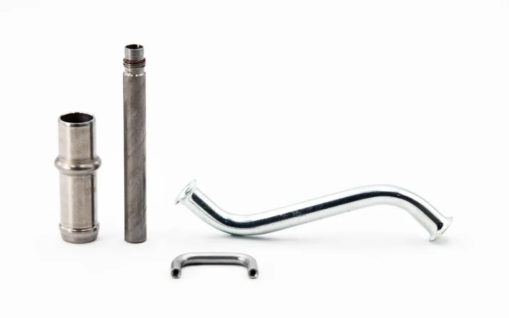
Short answer: hardware insertion is the process of installing PEM fasteners, rivet nuts, standoffs, studs, and other captive hardware into stamped sheet metal parts. The hardware is pressed into a prepared hole, and the displaced metal flows around the fastener features to create a permanent, torque-resistant assembly. Critical RFQ factors are hole size, material thickness, insertion force, pull-out torque, and installation method.
This guide is for design engineers, manufacturing engineers, and sourcing teams who need to specify PEM nut insertion, rivet nut installation, pressed standoffs, weld studs, or self-clinching fasteners in stamped sheet metal parts. Proper hardware insertion eliminates loose fasteners in assembly and provides reliable threaded attachment points in thin metal.
Send your drawing with hole specifications, hardware type, material, and thickness through the RFQ form. For related secondary operations, see stamped metal assemblies and secondary operations and metal stamping DFM review before tooling.
Common hardware types for stamped parts
| Hardware type | Installation method | Min material thickness | Typical application |
|---|---|---|---|
| Self-clinching nut (PEM type S, CLS) | Press into prepared hole | 0.8 mm | Threaded hole in thin sheet metal |
| Self-clinching standoff (PEM type SO, TSO) | Press into prepared hole | 0.8 mm | Spacing and mounting PCB standoffs |
| Self-clinching stud (PEM type FH, FHS) | Press into prepared hole | 0.8 mm | Threaded stud for bracket mounting |
| Rivet nut (also called blind rivet nut or threaded insert) | Pneumatic or manual rivet tool | 0.5 mm | Threaded hole in thin or blind-side sheet metal |
| Weld nut (projection weld) | Resistance welding | 1.0 mm | High-strength threaded attachment |
| Stamped or formed nut (integral) | Stamped in the same die | 0.5 mm (extruded) | Low-cost captive thread, low torque |
| Spring steel clip nut | Snap-on or press-in | 0.6 mm | Quick-assembly removable panels |
Self-clinching fasteners from PEM and equivalent brands are the most common choice for stamped parts in electronics enclosures, automotive brackets, and industrial equipment. For stamped clips and spring clips, see stamped metal clips and spring clips guide.
Hole preparation for self-clinching hardware
Hole quality directly affects the installation quality and retention strength of self-clinching hardware. Key requirements include:
- Hole size tolerance: PEM fasteners require hole diameters within ±0.03 to ±0.08 mm depending on fastener size. A hole that is too small prevents full seating of the fastener. A hole that is too large reduces retention force and can cause the fastener to spin in the sheet.
- Hole edge condition: the hole should be cleanly punched with consistent edge quality. Burr on the hole edge interferes with material flow during clinching and can prevent the fastener from seating flush. For burr control standards, see metal stamping burr control guide.
- Hole location relative to sheet edge: self-clinching fasteners need a minimum distance from the hole center to the sheet edge, typically 2-3 times the fastener head diameter. If the fastener is too close to the edge, the sheet may bulge or deform during installation.
- Deburring: deburr the hole on the fastener entry side. For high-volume production, the punch can be designed with a small chamfer to minimize burr on the entry side.
Hole preparation is typically done during the stamping process. Specify the hole punch station, clearance, and burr direction on the die design drawing. For hole and slot design, see punched holes and slots in stamped parts design guide.
Installation methods
The installation method depends on hardware type, production volume, and sheet metal thickness:
- Squeeze press (pneumatic or hydraulic): most common for self-clinching hardware in mid-to-high volume production. A pneumatic or hydraulic press with a custom anvil and punch nests the sheet, positions the hardware, and applies controlled force. Typical cycle time: 2-5 seconds per fastener.
- Hand-held pneumatic tool: used for low-volume assembly, service replacement, or large parts that cannot fit in a press. Installation quality depends on operator technique. Recommended only when a squeeze press is impractical.
- In-die insertion: advanced progressive dies can insert self-clinching hardware in the same press stroke as the stamping. This eliminates a separate work cell and reduces handling. Tooling cost is higher but per-part cost is lower at high volume.
- Robotic insertion: a robot positions the sheet and inserts hardware using an automated squeeze head. Suitable for large or complex parts where manual handling is inefficient.
For in-die insertion feasibility, consult with the stamper during the DFM review. For DFM guidance, see metal stamping DFM review before tooling.
Quality verification
Installed hardware should be verified for correct position, seating, and retention:
- Flushness: the fastener head should be flush with the sheet surface or within 0.1 mm. A raised fastener indicates incomplete insertion.
- Pull-out force: measure the axial force required to push the fastener out of the sheet. Minimum pull-out force varies by fastener size and material thickness. Test to the manufacturer specification.
- Torque test: apply the specified tightening torque to the threaded fastener. The fastener must not spin in the sheet. Spinning indicates hole size is wrong or installation force was insufficient.
- Sheet deformation: check for visible bulges or distortion around the fastener installation area. Bulging suggests the hole was too small or installation force was excessive.
- Crack test: for painted or coated parts, inspect the clinch area for cracks in the coating that could lead to corrosion.
For quality documentation requirements, see metal stamping first article inspection checklist.
Design considerations for hardware insertion
Minimum distance between fasteners. If multiple fasteners are installed close together, the displaced material from one installation can affect the adjacent hole condition. Minimum center-to-center distance is typically 3-4 times the fastener head diameter.
Thread locking. Self-clinching fasteners are available with thread-locking features (nylon patch, deformed threads, or dry adhesive). For applications where vibration loosening is a concern, specify a locking element on the fastener drawing.
Material compatibility. The sheet material must be ductile enough to flow during clinching without cracking. Low-carbon steel, most stainless steels, aluminum 5052-H32, and brass are all compatible. High-strength steels with limited ductility may not be suitable for self-clinching hardware. For material guidance, see metal stamping material selection guide.
Corrosion protection. If the stamped part is plated or coated after hardware insertion, the coating can wick into the thread area, interfering with fastener function. Install hardware after plating when possible, or specify thread protection. For coating details, see metal stamping plating and passivation RFQ guide.
RFQ checklist for hardware insertion
- Drawing showing hardware type, location, orientation, and hole size for each installed fastener.
- Sheet material: grade, thickness, temper, and coating.
- Hardware: brand, part number, material, and finish if not standard.
- Annual volume and order quantity.
- Required pull-out force and torque resistance per fastener.
- Installation method preference: squeeze press, in-die, robotic, or hand tool.
- If in-die insertion is desired, confirm tooling budget and timeline.
- Quality: flushness, pull-out test frequency, and reporting format.
- Packaging: bulk, separated bins, or kitted to prevent hardware mix.
Submit your stamped part drawing with hardware specifications through the RFQ form. For general RFQ preparation, see the metal stamping RFQ checklist.