
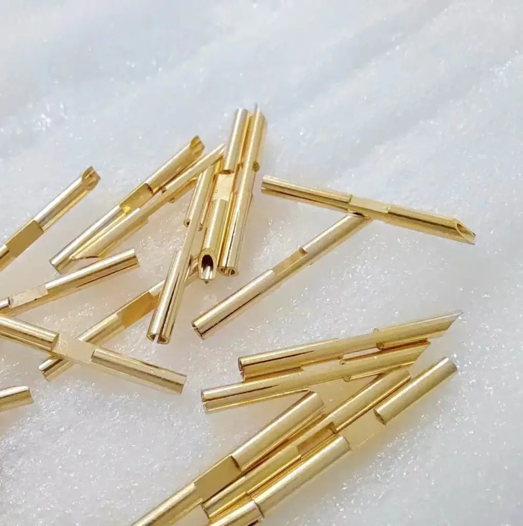
Short answer: Stamped terminals supplied on carrier strip should be quoted with the cutoff tab, pitch, feed direction, burr side, reel orientation, and applicator trial condition. A terminal can pass loose-part inspection but still jam, misfeed, expose sharp cutoff burrs, or damage wire strands if the carrier and tab rules are not defined before tooling.
The small tab left after a terminal is cut from carrier strip can decide whether a crimp line runs cleanly. Too long, too sharp, bent the wrong way, or located near the functional zone, it can interfere with feeding, connector insertion, wire insulation, or operator handling.
Use this page with the wire harness stamped terminals guide, crimp pull-force guide, terminal and contact design guide, and progressive die strip layout guide.
Carrier and cutoff tab RFQ details
| Detail | Why it matters | RFQ evidence |
|---|---|---|
| Pitch and feed direction | Applicators and automated feeders depend on stable pitch. | Strip drawing, feed hole detail, feed direction, and reel orientation. |
| Cutoff tab length | A long tab can catch; a short tab can create weak handling or separation issues. | Nominal and maximum tab length with measurement point. |
| Burr side | A burr can cut wire strands, scrape plating, or block connector seating. | Preferred burr direction, maximum burr, and edge break if required. |
| Trial condition | Loose samples do not prove reel feeding or crimp setup. | Reel sample, leader length, splice rule, and applicator or crimp trial evidence. |
Design the carrier around the downstream process
Carrier strip is not only scrap between terminals. It controls pitch, orientation, plating access, inspection handling, reel winding, and the final cutoff point. If the buyer already has an applicator, feeder, or connector assembly machine, that equipment should be shared before the progressive die layout is final.
The carrier may need feed holes, pilot holes, pull tabs, breakaway bridges, or protected areas for selective plating. The location of the cutoff tab should avoid contact surfaces, crimp barrels, locking lances, and any edge that touches insulation. If crimping is part of the launch risk, connect the quote to the incoming inspection checklist and define what the buyer will measure at receiving.
Include burr and plating evidence
Cutoff burrs can be worse than blanking burrs because the final separation happens at the applicator or a secondary cutting station. If the tab edge points toward a wire, plastic cavity, mating surface, or operator hand, the drawing should state the preferred burr side and the allowed maximum.
Plating should also be reviewed around the tab. Pre-plated strip may leave exposed base metal at the cut edge. Post-plating can cover more edges, but may require different handling and masking. If the part is small, plating buildup can change crimp wing behavior or connector fit. For finish choices, use the copper terminal plating guide and the selective plating guide.
RFQ details to include
- Terminal drawing, flat strip layout if available, crimp barrel details, locking lance, contact zone, and cutoff tab location.
- Material, thickness, temper, plating stack, selective plating zones, burr direction, and edge requirements.
- Pitch, feed holes, carrier width, feed direction, reel direction, leader length, tail length, splice rule, and quantity per reel.
- Cutoff tab nominal and maximum length, acceptable rollover, visual standard, and whether the tab is checked after applicator separation.
- Crimp trial needs, wire gauge range, pull-force limit, cross-section evidence, sample reel quantity, and report format.
- Annual volume, launch timing, applicator model if known, and current feeding or crimp issue history.
How to compare supplier answers
A useful answer asks about the applicator and reel condition, not just the terminal drawing. It should explain how the carrier will be piloted, where the tab will break, and how tab burrs are checked. A weak answer treats the carrier as a tooling detail that the buyer does not need to review.
Ask for a short pilot run on reel when feeding risk matters. Loose terminals can hide pitch wander, twist, tab burr, and reel memory problems. If the terminal goes into a harness line, align the sample plan with the line trial rather than a bench-only inspection.
Send terminal drawings, strip requirements, wire data, reel rules, cutoff tab limits, and trial needs through the contact page. Use the RFQ form to ask whether tab length and burr evidence can be included in the first article report.
FAQ
Why is the cutoff tab important on stamped terminals?
The tab can affect feeding, crimp quality, connector insertion, wire insulation, handling safety, and plating exposure after the terminal is separated from the carrier.
Can a stamped terminal be approved as a loose sample?
Loose samples help check geometry, but terminals supplied on reels should also be checked for pitch, orientation, leader length, splice rules, and cutoff behavior.
What causes terminal reel feeding problems?
Common causes include pitch variation, bent carrier strip, wrong reel direction, poor splice control, twist, cutoff tab interference, burrs, or applicator mismatch.
What should be sent for a carrier strip RFQ?
Send terminal drawings, strip layout, pitch, feed direction, reel orientation, plating, burr direction, cutoff tab limits, wire data, sample reel needs, and volume.