Progressive die stamping is the most efficient and cost-effective metal stamping process for high-volume production of complex parts. Using a series of stamping stations arranged in sequence within a single die, progressive stamping performs multiple operations — blanking, piercing, bending, coining, and forming — with each press stroke, producing a finished part at the end of every cycle.
As an experiencstamping manufactureramping manufacturer, we design, build, and run progressive dies for customers in the automotive, electronics, appliance, medical, and industrial sectors. Our progressive stamping capabilities deliver parts with tight tolerances, complex geometries, and excellent surface finishes at production rates up to 1,500 strokes per minute.
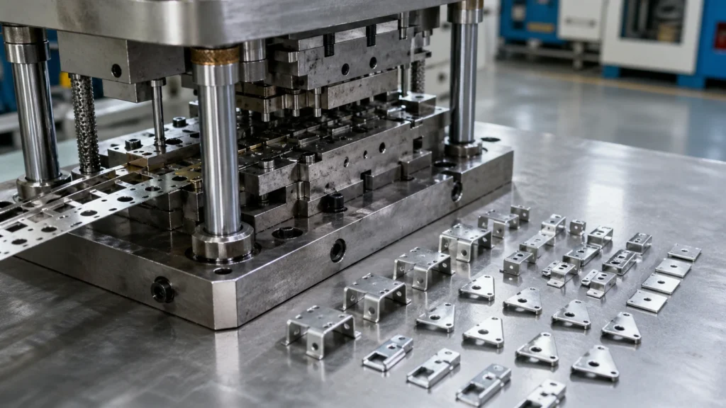
How Progressive Die Stamping Works
In progressive die stamping, a continuous strip of metal (coil stock) feeds through a die mounted in a stamping press. The die contains multiple stations, each designed to perform a specific operation on the metal strip. As the press cycles, the strip advances a precise distance (called the pitch) to the next station, where a new operation is performed on the advancing strip.
At the first station, the strip may be pierced with pilot holes for precise alignment. Subsequent stations perform blanking, piercing, bending, forming, coining, or embossing operations. At the final station, the finished part is cut free from the carrier strip. This entire sequence happens with every press stroke, producing one or more finished parts per cycle.
The key elements of progressive die design include:
- Strip layout — the arrangement of part features across the strip width, optimized to minimize material waste
- Station sequence — the order of operations designed to maintain strip integrity and part accuracy throughout the process
- Pilot system — pins that register the strip at each station for precise alignment
- Carrier strip — the portion of the metal strip that carries the partially-formed part between stations
- Scrap management — designed-in slug removal and scrap chutes to prevent die damage
Advantages of Progressive Die Stamping
- High production speed — 100 to 1,500+ strokes per minute depending on part complexity and material
- Consistent quality — repeatable tolerances of ±0.001 inches across millions of parts with minimal operator intervention
- Lower per-part cost — minimal material waste, reduced labor, and no part handling between operations
- Complex geometries — multiple operations in one die eliminate the need for separate secondary processes
- Material efficiency — optimized strip layout typically achieves 75-85% material utilization
- Reduced handling — parts are formed in a continuous process, eliminating damage from inter-operation handling
- Automation friendly — coil feeding, part ejection, and scrap removal are easily automated
Progressive Die Stamping Applications
Progressive metal stamping is widely used across industries for parts that require high volumes, tight tolerances, and complex features:
- Automotive — electrical terminals, connector housings, brackets, clips, retainers, and seat components
- Electronics — connector contacts, LED lead frames, EMI/RFI shielding, heat sinks, and battery contacts
- Appliance — motor laminations, switch components, brackets, and internal structural parts
- Medical — surgical instrument components, implant parts, and precision metal stamping springs
- Industrial — electrical contacts, fasteners, hinges, and hardware components
Our Progressive Die Stamping Capabilities
| Capability | Specification |
|---|---|
| Press capacity | 25 to 400 tons |
| Press speed | Up to 1,500 strokes per minute |
| Material thickness | 0.004 inches to 0.250 inches |
| Strip width | Up to 24 inches |
| Tolerances | ±0.001 inches on critical dimensions |
| Materials | Steel, stainless steel, aluminum, brass, copper, specialty alloys |
| Die stations | Up to 30+ stations per die |
| Production volume | Prototype to 10,000,000+ parts annually |
In-House Progressive Die Design and Build
Transfer Die Stampingng team designs and builds progressive dies in-house, giving us complete control over die quality, lead time, and cost. Using SolidWorks 3D modeling and stamping simulation software, we optimize every die design for part quality, die life, and production efficiency before cutting any steel. Our in-house die shop is equipped with wire EDM, CNC machining centers, and precision surface grinders.
Progressive Die Stamping vs. Other Processes
How does progressive die stamping compare to other manufacturing methods?
| Factor | Progressive Die | Transfer Die | CNC Machining |
|---|---|---|---|
| Best volume range | 10,000 to millions | 1,000 to 100,000 | 1 to 5,000 |
| Part size | Small to medium | Medium to large | Any size |
| Speed (parts/hour) | 6,000 to 90,000 | 1,200 to 4,800 | 5 to 50 |
| Tooling cost | Higher | Moderate | Low/None |
| Per-part cost at volume | Lowest | Low | Highest |
| Complexity | High | High | Very High |
Read our detailed comparison: Progressive Die vs. Transfer Die Stamping.
Frequently Asked Questions
What is progressive die stamping?
Progressive die stamping is a metalworking method that uses a series of stamping stations arranged in sequence within a single die. A continuous strip of metal passes through each station where different operations (blanking, piercing, bending, forming) are performed, producing a finished part with each press stroke.
What tolerances can progressive die stamping achieve?
Progressive die stamping can achieve tolerances as tight as ±0.001 inches (±0.025mm), depending on material type, thickness, and part geometry. Standard commercial tolerances are typically ±0.005 inches.
What is the minimum order quantity for progressive die stamping?
Progressive die stamping is most cost-effective for volumes of 10,000 parts or more, though we can accommodate smaller runs for prototyping and pre-production. The higher the volume, the lower the per-part cost as tooling investment is amortized across more units.
How long does it take to build a progressive die?
Typical progressive die build time is 4-8 weeks depending on complexity and number of stations. Simple dies with fewer stations may be completed in 3 weeks, while complex dies with 20+ stations may require 10-12 weeks.
Request a Quote for Progressive Die Stamping
Send us your part drawings or 3D models. Our engineering team will evaluate your design and provide a competitive quote for progressive die stamping production, including tooling costs, unit pricing, and lead time.
Email: [email protected] | Phone/WhatsApp: +86 152-5047-1868
Related Resources
Our progressive die heavy metal stamping services handle material thicknesses up to 6.0 mm in steel and 8.0 mm in aluminum, using 200–400 ton presses with servo feeds and in-die tapping capability. We also operate as a turnkey progressive die stamping manufacturer — from tooling design and die build through production, secondary operations, surface finishing, and assembly — so you get finished parts from a single source with one point of quality accountability.