
Metal forming is the process of reshaping flat sheet metal or coil stock into three-dimensional parts through controlled plastic deformation. Unlike cutting or machining operations that remove material, forming changes the shape of the metal while preserving its volume. The result is a structural or functional part with geometry, strength, and surface condition defined by the tooling and press parameters.
We provide metal forming services as part of our stamping and precision manufacturing capabilities. Forming operations are used independently and in combination within progressive, compound, and transfer die tooling to produce complex parts in a single controlled sequence.
Need a formed metal part? Send your drawing, material, thickness, and volume to our contact page for a forming review and quote.
Metal Forming Operations We Support
Metal forming covers a broad range of operations. The most common in our stamping and sheet metal manufacturing scope include:
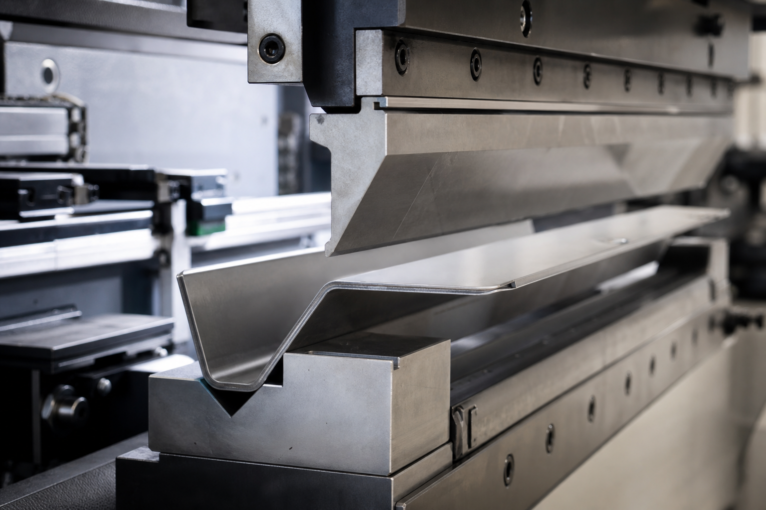
Bending
Bending applies force to create an angle or curved profile in flat metal. Common bending operations include V-bending, U-bending, and wipe bending. Springback must be compensated in the tooling design based on material grade and thickness. Key design considerations include minimum bend radius (typically 1× material thickness for ductile metals), and maintaining consistent grain direction relative to the bend axis.
Deep Drawing
Deep drawing uses a punch and die to pull flat sheet metal radially inward, forming cups, shells, and cylindrical housings. The process is characterized by the draw ratio, which defines the ratio of blank diameter to punch diameter. Material must have sufficient elongation to complete the draw without tearing. Flanges, walls, and bases can all be held to tight dimensional tolerances in properly designed draw tooling. See also: deep draw stamping.
Coining
Coining uses very high pressure to precisely size a feature by compressing the metal between punch and die faces. The result is a dimensionally stable, burr-free surface on the coined area. Coining is used on features where tight dimensional control, sharp radii, and surface quality matter more than general forming tolerance. It is commonly applied to terminal faces, contact points, and critical seating surfaces.
Embossing
Embossing displaces metal to create raised or recessed features such as logos, stiffening ribs, identification markings, or registration features. The material is not removed — only locally shaped into a raised pattern. Embossed features add structural stiffness to thin parts without adding weight.
Flanging
Flanging bends the edge of a flat or formed part outward or inward to create a flange. Flanges are used for structural stiffening, assembly interfaces, sealing surfaces, or edge protection. Extruded holes (where a punched hole is flanged outward to create a threaded boss) are a related operation.
Forming and Offsetting
General forming operations reshape a blank into complex non-flat profiles. Offset forming creates Z-profiles or stepped features in otherwise flat parts. These are common in connector housings, brackets, and assembly supports.
Ironing
Ironing uniformly reduces the wall thickness of a drawn shell to tighten dimensional tolerances on the outer diameter or inner bore. Often used as a secondary operation after deep drawing to achieve precise wall geometry.
Materials Used in Metal Forming
Formability depends heavily on material ductility, thickness, grain structure, and temper condition. We form parts in:
| Material | Forming Notes | Typical Formed Parts |
|---|---|---|
| Carbon steel (SPCC, DC01) | Good formability; may springback; weldable | Brackets, structural shells, covers |
| Stainless steel (304, 301) | Higher springback; work hardens; stronger after forming | Medical housings, food hardware, corrosion-sensitive shells |
| Aluminum (5052, 3003) | Excellent ductility; low springback; lightweight | Electronics enclosures, automotive covers, aerospace housings |
| Copper (C11000) | Very high formability; excellent for deep draw and coining | Terminals, contacts, electrical shells |
| Brass (C26000) | Good formability; surface stability after forming | Connector components, decorative formed parts |
Material-specific pages: aluminum stamping, stainless steel stamping, steel stamping, copper stamping, and brass stamping.
Metal Forming in Stamping Processes
Metal forming operations are rarely standalone. In production stamping, they are integrated into the tooling sequence:
- In progressive die stamping, forming stages are distributed across stations on a continuous strip, allowing blanking, piercing, bending, and coining to occur in sequence within a single tool
- In transfer die applications, the blank is physically moved between forming stations, allowing more complex geometry that cannot be achieved on a strip
- In compound dies, blanking and forming happen simultaneously in a single stroke, suited for flat or lightly formed parts
- In deep draw processes, the forming sequence controls draw depth, wall thickness consistency, and flange geometry across multiple stages
DFM Considerations for Formed Parts
Forming design affects tooling complexity, part consistency, and production cost. Important DFM considerations include:
- Minimum bend radius — too tight a radius causes cracking or fracture; typically 0.5–1× material thickness minimum depending on alloy
- Springback compensation — overbending angle must be calculated per material and thickness to achieve the specified angle after release
- Grain direction vs. bend axis — bending perpendicular to grain direction reduces cracking risk in work-hardened materials
- Feature proximity — holes placed too close to a bend line distort during forming; maintain minimum distance of 1.5× material thickness from edge
- Formed depth vs. material thickness — deep draw ratios must be matched to material elongation capacity
- Symmetry and balance — asymmetric forming loads cause strip or blank shifting; tooling must compensate with balanced die geometry
Industries Using Metal Forming Services
- Automotive — body stampings, seat brackets, structural supports, clip formed parts. See: automotive stamping
- Electronics — terminal shells, EMI housings, connector bodies, precision contacts. See: electronics stamping
- Medical — precision formed stainless parts, drawn housings, surgical instrument components. See: medical device stamping
- Aerospace — structural stampings, enclosure panels, formed support parts. See: aerospace metal stamping
- Home appliances — motor parts, control panels, formed housings. See: home appliance stamping
- Construction — formed support hardware, anchor plates, brackets. See: construction metal stamping
FAQ: Metal Forming
What is metal forming in stamping?
Metal forming in stamping refers to press-based operations that reshape sheet metal without removing material. This includes bending, drawing, coining, embossing, flanging, and offsetting. Forming operations are often combined within progressive or compound die tooling.
What is the difference between metal forming and metal cutting?
Metal cutting operations (blanking, punching, shearing) separate material by fracture or shear. Metal forming operations reshape material through plastic deformation without separation. Most stamped parts require both cutting and forming operations within the same tool.
What metals are easiest to form?
Copper, aluminum, and low-carbon steel have the highest ductility and form most easily. Stainless steel and high-strength steel alloys have more springback and require more precise tooling compensation. Material temper and grain structure also affect formability significantly.
What tolerances can be held on formed parts?
Standard formed features typically hold ±0.1–0.3 mm depending on part complexity. Coined surfaces can hold ±0.01–0.05 mm. Angular tolerances on bends typically range from ±0.5° to ±2° depending on material and forming method.
How do I reduce springback on formed parts?
Springback is reduced through overbending in tool design, coining the bend radius, designing with tighter radii, or using materials with lower elastic modulus. DFM review should address springback prediction before tooling is built.
Request a Metal Forming Quote
Whether you need a simple bend or a complex deep-draw shell, our forming process starts with understanding your part’s functional requirements and tolerance needs. We review the drawing, confirm the forming approach, and provide a tooling and production plan that supports long-term manufacturability.
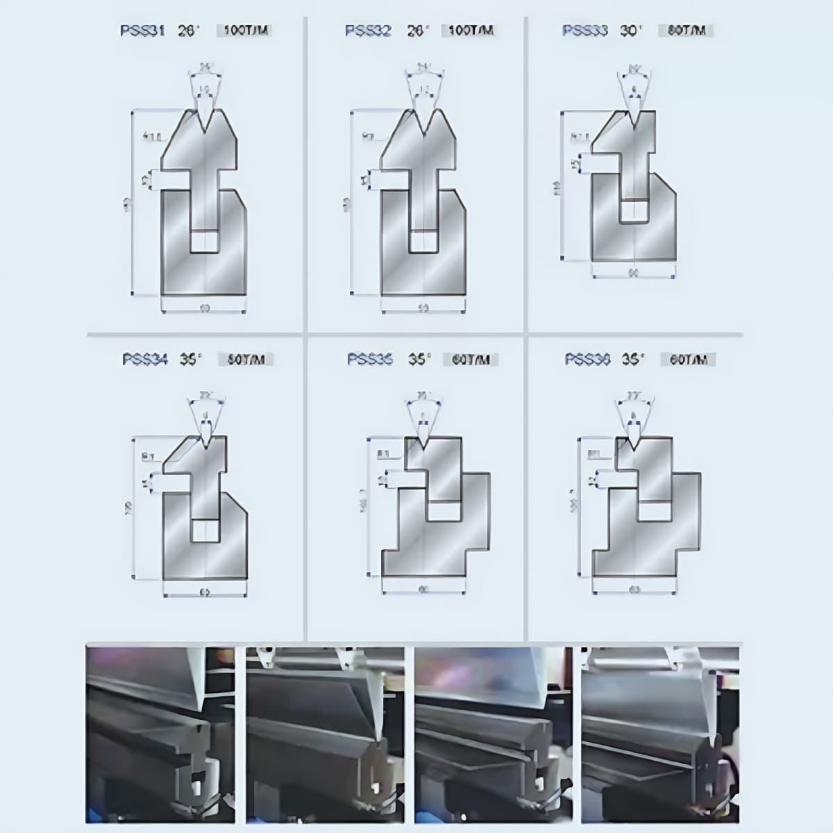
Tooling Design for Metal Forming Operations
The quality of a formed part starts with the tooling design. Every forming operation — whether it is a simple 90° bend or a complex multi-stage draw — requires tooling geometry that accounts for material behavior, springback, and dimensional requirements:
- Bend radius and die opening — the ratio of die opening to material thickness (V-die width) determines the bending force required and the inside radius of the bend. Smaller die openings produce tighter radii but require higher force and increase the risk of surface marking.
- Springback compensation — all metals exhibit elastic recovery after forming. The tooling must overbend the part by the predicted springback amount so that the finished part returns to the target angle after unloading. Springback prediction is material-specific and is validated during pilot production.
- Draw die design — deep drawing operations require careful control of blank holder pressure, punch radius, and die radius to prevent tearing, wrinkling, and orange-peel surface defects. Draw ratio limits depend on material ductility and thickness.
- Coining and sizing tools — when formed features need tighter tolerances than standard forming can achieve, coining tools compress the material to a precise thickness or surface level. This adds a station to the die but can achieve ±0.01–0.03 mm on coined surfaces.
- Multi-stage forming sequences — complex geometries that cannot be formed in a single hit require multiple forming stations within a progressive or transfer die. Each station incrementally shapes the material to avoid over-stressing any single area.
Tooling design for forming operations is where engineering capability directly affects part quality and production stability. We design all forming tooling in-house to maintain control over the forming sequence and springback compensation strategy.
Material Behavior in Forming Operations
Different metals respond differently to forming stress. Understanding material behavior is essential for designing forming tooling that produces consistent parts:
- Yield strength and tensile strength — higher-strength materials require more forming force and exhibit more springback. Materials above 500 MPa tensile strength often need adjusted die clearances and tighter process control.
- Elongation and reduction of area — these measures of ductility determine how much a material can be stretched or drawn before fracture. Low-elongation materials limit the depth of draw and the tightness of bend radii.
- Strain hardening exponent (n-value) — materials with higher n-value distribute deformation more evenly, which is beneficial for drawing and stretching operations. Low n-value materials tend to localize deformation and neck earlier.
- Plastic strain ratio (r-value) — indicates the material’s resistance to thinning during drawing. High r-value materials draw more successfully and are preferred for deep-draw applications.
- Surface condition and coating — surface roughness, oil coating, and galvanized layers all affect friction during forming. Tool surface treatment and lubrication must be matched to the material surface condition.
Material data from mill certificates and our internal testing database is used during DFM review to predict forming behavior and set realistic tolerance expectations before tooling design begins.
Frequently Asked Questions
What is metal forming in stamping?
Metal forming in stamping refers to press-based operations that reshape sheet metal without removing material. This includes bending, drawing, coining, embossing, flanging, and offsetting. Forming operations are often combined within progressive or compound die tooling.
What is the difference between metal forming and metal cutting?
Metal cutting operations (blanking, punching, shearing) separate material by fracture or shear. Metal forming operations reshape material through plastic deformation without separation. Most stamped parts require both cutting and forming operations within the same tool.
What tolerances can be held on formed parts?
Standard formed features typically hold ±0.1–0.3 mm depending on part complexity. Coined surfaces can hold ±0.01–0.05 mm. Angular tolerances on bends typically range from ±0.5° to ±2° depending on material and forming method.
How do I reduce springback on formed parts?
Springback is reduced through overbending in tool design, coining the bend radius, designing with tighter radii, or using materials with lower elastic modulus. DFM review should address springback prediction before tooling is built.
What metals can be formed by stamping?
Cold-rolled steel, stainless steel, aluminum alloys, copper, brass, phosphor bronze, and pre-coated steels can all be formed by stamping. Each material has different forming limits, springback characteristics, and tooling requirements that are evaluated during DFM review.
Can you form complex 3D shapes by stamping?
Yes. Complex 3D shapes are produced through multi-stage forming sequences within progressive or transfer die tooling. Deep drawing, stretch forming, and staged bending can create geometries that would be difficult or expensive to produce by machining or casting.
Contact us to start your metal forming project — send your drawing, material, and volume and we will respond with a review and quote.