
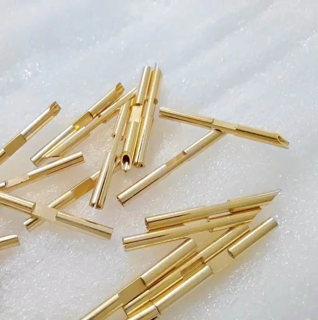
Short answer: Press-fit compliant pins should be quoted with insertion force, retention force, PCB hole condition, and test evidence, not only pin geometry. The RFQ should define the compliant zone, board hole size and plating, pin material, finish, insertion depth, fixture, insertion speed, sample state, retention limit, and whether electrical resistance is checked after insertion.
A broad press-fit pin drawing can still leave the most important production question unanswered: will the pin insert into the real PCB without damaging the hole and still hold after vibration, heat, or handling? This page narrows the discussion to force testing and acceptance evidence.
Use this page with the press-fit stamped pins guide, terminal and contact design guide, contact resistance test guide, and terminal plating thickness inspection guide.
Press-fit force details before quoting
| Detail | Why it matters | RFQ evidence |
|---|---|---|
| PCB hole condition | Drill size, copper plating, tin finish, and board thickness change insertion force. | Finished hole range, plating stack, board thickness, and test coupon rule. |
| Compliant zone | Eye-of-the-needle, split beam, and formed pin sections deform differently. | Pin section drawing, material temper, burr side, and formed width. |
| Insertion force | Too much force can damage holes or bend pins; too little can signal weak contact. | Peak force, insertion depth, speed, fixture, and sample quantity. |
| Retention evidence | A pin can insert cleanly and still fail push-out or vibration retention. | Push-out or pull-out direction, limit, post-aging condition, and report format. |
Separate the pin quote from the board test
The stamping සැපයුම්කරු controls strip material, pin geometry, burr direction, plating, and carrier handling. The final press-fit result also depends on the PCB hole tolerance, copper plating thickness, solder mask clearance, insertion tool, support fixture, and board stack-up. The RFQ should state whether the සැපයුම්කරු is only making pins or also validating inserted samples.
If the board is not ready, ask for testing in a representative coupon and label the result as preliminary. When the real PCB changes, insertion force and retention should be confirmed again. For board-related contact concerns, connect the plan to the coplanarity guide and the functional gage guide.
Define what is measured after insertion
A clean insertion curve is useful, but it does not prove long-term electrical function by itself. For signal pins, low and stable contact resistance may matter. For power or ground pins, current path, heat rise, and contact area can matter more. If the pin is exposed to vibration, pair force testing with a vibration or continuity check.
The finish should also be discussed before tooling is frozen. Tin may be common, but plating thickness, underplate, whisker risk, and storage condition can affect both force and contact behavior. If the pin will sit in inventory before insertion, include shelf-life and packaging controls.
RFQ details to include
- Pin drawing with compliant section, insertion depth, burr side, carrier tab, and functional contact zone.
- Material grade, thickness, temper, plating stack, underplate, and whether selective plating is used.
- PCB finished hole size, board thickness, plating stack, solder mask clearance, and coupon or real-board test condition.
- Insertion force limit, retention or push-out limit, test speed, fixture support, sample size, and report format.
- Electrical resistance, continuity, heat aging, vibration, or cycling requirement if the connection is safety or signal critical.
- Annual volume, prototype quantity, reel format, packaging rule, and target launch date.
How to compare සැපයුම්කරු answers
A useful answer separates pin-making variables from PCB and assembly variables. Look for comments about pin width, burr direction, plating thickness, insertion tooling, and what board data is still needed. A weak answer only says the pin is compliant.
Ask how the සැපයුම්කරු handles force results outside the target window. The answer should separate stamping variation, plating buildup, PCB hole variation, insertion fixture error, and sample handling. This makes trial builds easier to diagnose.
Send pin drawings, PCB hole data, force limits, and report needs through the contact page. If the board stack-up is not final, use the RFQ form to request a staged validation plan before production tooling is locked.
FAQ
What causes high insertion force on press-fit pins?
Common causes include oversized pin geometry, plating buildup, tight PCB holes, poor board support, burr direction, tool misalignment, or an insertion depth that exceeds the compliant zone design.
Is retention force enough to approve a press-fit pin?
Not by itself. Retention should usually be paired with insertion force, visual hole inspection, pin straightness, and electrical resistance or continuity when function depends on the connection.
Should press-fit pins be tested in a coupon or the real PCB?
Use the real PCB when available. Coupons are useful early, but hole plating, board thickness, and fixture support must represent the final assembly.
What should be sent for a press-fit force RFQ?
Send pin drawings, material, plating, board finished hole data, insertion depth, insertion and retention limits, sample quantity, report needs, and annual volume.