
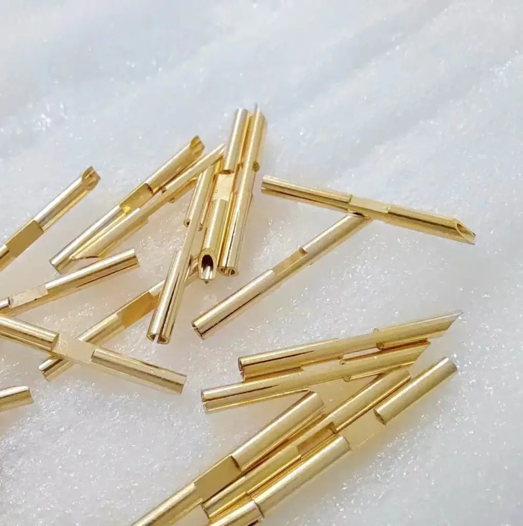
Short answer: press-fit stamped pins are formed metal terminals that are pressed into plated through-holes in a PCB without soldering. The pin has a compliant section (eye-of-the-needle, split beam, or solid press-fit) that deforms elastically during insertion, creating a gas-tight mechanical and electrical connection. The critical RFQ factors are pin material, plating, compliant zone geometry, insertion force, retention force, and hole size tolerance.
This guide is for connector design engineers, PCB assembly buyers, and automotive electronics sourcing teams who need to specify stamped press-fit pins, compliant pin terminals, eye-of-the-needle contacts, and solderless PCB terminals for high-reliability electronic assemblies.
Send drawings with pin geometry, PCB hole size, material, plating, and insertion requirements through the RFQ form. For related connector parts, see terminal and contact stamping design guide and electrical connector shield stamping guide.
Common press-fit pin applications
- Automotive ECU and module connectors where vibration resistance and lead-free assembly are required.
- Backplane and server connector pins for high-density PCB interconnects in data centers.
- Industrial control module connectors for PLC, drive, and I/O systems.
- Battery management system (BMS) signal and power pins for EV battery packs.
- Telecom base station connector pins for 5G and RF module interconnects.
- Medical device connector pins where soldering is avoided due to heat sensitivity.
For EV battery-related connections, see EV battery stamping parts and busbars and copper busbar stamping RFQ guide.
Press-fit pin design types
| Type | Compliant feature | Typical PCB hole size | Retention force |
|---|---|---|---|
| Eye-of-the-needle (EON) | Slot through the pin body creates two spring beams | 0.6 – 1.0 mm | 15 – 50 N |
| Split-beam compliant pin | Slotted tip with expanded bulb section | 0.8 – 1.5 mm | 20 – 60 N |
| Solid press-fit pin | Interference fit only (no compliant feature) | 0.5 – 1.0 mm | 10 – 30 N |
| Action pin (multi-beam) | Multiple spring beams around the pin circumference | 0.7 – 1.2 mm | 20 – 80 N |
| Stamped formed pin | Pin formed from flat strip into a box or U-section | 0.6 – 1.5 mm | 10 – 40 N |
Eye-of-the-needle pins are the most common type for automotive and industrial connectors because they provide consistent retention force across a range of PCB hole sizes. Stamped formed pins are cost-effective for high-volume applications where pin density is moderate.
Materials for press-fit pins
The material must provide sufficient spring force in the compliant section without taking a permanent set during insertion:
- Phosphor bronze (C510, C521) — most common for press-fit pins. Good spring properties, moderate conductivity, and good solderability if secondary soldering is needed. Fatigue strength supports multiple insertion cycles.
- Brass (C260, C268) — lower cost but also lower spring force. Suitable for larger pin cross-sections or lower retention force requirements.
- Beryllium copper (C172) — best spring properties and fatigue life. Used for high-reliability automotive or aerospace applications where retention force must not degrade over product life.
- Copper-nickel-silicon alloy (C7025) — high strength with good conductivity. Increasingly used in EV and high-current connector applications.
- Stainless steel 301 (full hard) — for non-magnetic or corrosion-resistant applications. Lower conductivity, thicker cross-section needed for current-carrying pins.
For spring material properties, see phosphor bronze and beryllium copper contact stamping.
Plating requirements
Press-fit pins rely on the plating for low contact resistance, corrosion protection, and wear resistance during insertion:
- Tin plating (matte) — most common for press-fit pins. 1-3 microns typical. Matte tin preferred over bright tin to reduce whisker risk. The tin deforms during insertion, creating a gas-tight interface.
- Gold over nickel — for low-signal-level or high-reliability applications. 0.5-1.5 microns gold over 1-3 microns nickel underplate. Used in automotive ADAS, medical, and aerospace.
- Silver plating — for high-current pins where conductivity matters more than corrosion resistance. 2-5 microns typical.
- Palladium-nickel or palladium-silver — alternative to gold for harsh environments where tin would corrode.
Selective plating is common for press-fit pins to reduce cost. Only the compliant zone and contact area are plated. For plating specifications, see ලෝහ මුද්රා තැබීම plating and passivation RFQ guide.
Insertion and retention force
Press-fit pin performance is defined by insertion force (force required to press the pin into the PCB hole) and retention force (force required to pull the pin out after insertion). Key guidelines include:
- Insertion force is typically 1-3 times retention force, depending on pin geometry and hole size tolerance.
- For automotive applications, IPC-6012 and USCAR-2 specify minimum retention forces per pin cross-section. A typical 0.6 mm square pin must retain at least 15 N after environmental cycling.
- Retention force should not degrade more than 20% after 3 insertion-retraction cycles.
- The PCB hole diameter tolerance is critical: a ±0.05 mm change in hole diameter can change retention force by 30-50%. Specify hole size acceptance limits with the customer.
For related quality standards, see PPAP and APQP for metal මුද්රා තැබූ කොටස්.
Tolerances for press-fit pins
- Pin width at compliant section: ±0.03 mm for precision tooling.
- Pin thickness (material gauge): ±0.02 mm.
- Slot width in eye-of-the-needle type: ±0.03 mm.
- Tip radius and chamfer: ±0.05 mm. Tip chamfer must be consistent to guide the pin into the PCB hole without skiving.
- Co-planarity after strip cutoff: 0.10 mm max for tape-and-reel delivery.
- Burr on contact surface: 0.03 mm max. Burr on the compliant zone can increase insertion force or damage the PCB through-hole plating.
For comprehensive tolerance standards, see ලෝහ මුද්රා තැබීම tolerances guide.
Packaging for automated assembly
Press-fit pins for automated insertion are almost always supplied on tape-and-reel (carrier tape). Key packaging specifications include:
- Reel quantity: typically 1,000-10,000 pins per reel, depending on pin size.
- Carrier tape material: conductive or anti-static plastic to prevent ESD damage.
- Pin orientation: each pin must be correctly oriented for the pick-and-place head. The embossed pocket or heat-sealed cover tape must hold the pin securely during shipping and handling.
- Splice frequency: specify maximum number of splices per reel and leader/trailer length.
For packaging details, see ලෝහ මුද්රා තැබීම packaging and shipping guide.
RFQ checklist for press-fit pins
- Drawing with pin geometry, compliant zone detail, tip chamfer, and overall dimensions.
- Material: alloy, temper, and thickness.
- Plating: type, thickness, and plated zones (full or selective).
- PCB hole size: nominal diameter, tolerance, and plated through-hole thickness.
- Insertion and retention force requirements, including test method.
- Annual volume and packaging format.
- Automotive or industry standard compliance (USCAR-2, IPC, LV214).
- Maximum allowable burr height and location.
- Target price or budget range for per-part cost.
Submit your press-fit pin drawings through the RFQ form. For RFQ preparation, see the ලෝහ මුද්රා තැබීම RFQ checklist.