
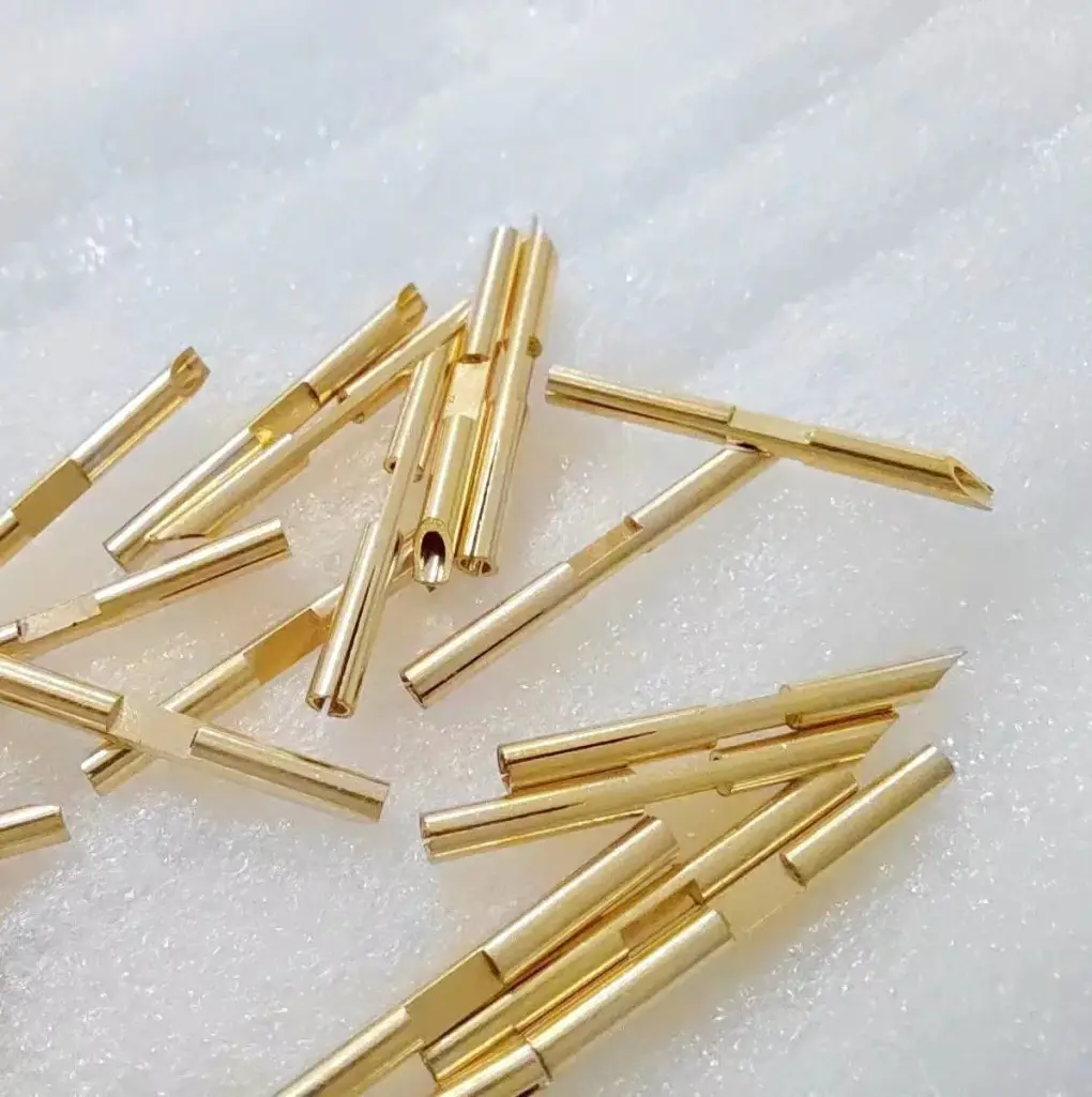
Short answer: stamped metal grounding clips are spring contact parts that create a repeatable conductive path between a board, shield, chassis, enclosure, rail, or frame and ground. A useful RFQ should define the drawing, material and temper, thickness, plating, contact force target, grounding path, burr direction, assembly method, packaging, inspection, volume, and akoko ifijiṣẹ.
This guide is for engineers and sourcing teams buying grounding clips, EMI grounding contacts, chassis clips, electrical spring contacts, and stamped conductive parts. The buying question is usually contact reliability: will the clip keep enough force and conductivity after forming, plating, assembly, shipping, and use?
For a quote, send drawings, mating part details, material preference, plating, contact force target, grounding path, inspection needs, packaging, volume, and schedule through the RFQ form. For related small electrical parts, see the terminal and contact stamping guide and the small electronics stamping guide.
What buyers usually need from a grounding clip
A stamped grounding clip may connect a PCB ground pad to a chassis, bond a removable cover to an enclosure, maintain contact between a shield can and a frame, or provide a spring path in an electronic assembly. Unlike a broader EMI shielding stamped part, the main function is usually a controlled conductive path through a specific contact point.
The drawing should show the grounding path, mating surface, free height, working height, stop features, and keep-out zones. The RFQ should also make clear whether the part is a prototype, pilot run, or production item suitable for irinṣẹ ìtẹ ìtẹ̀síwájú stamping. If the design is still flexible, a DFM review through custom ìtẹ irin can help confirm bend radius, strip layout, burr direction, and plating sequence before tooling is committed.
Common applications and part types
- PCB-to-chassis grounding clips for electronics housings and control modules.
- Spring contacts for covers, frames, shield cans, card cages, and enclosure joints.
- Stamped chassis clips used where screws, weld studs, or loose wires add assembly time.
- Battery, terminal, and electrical spring contacts where current path and spring recovery both matter.
- Conductive clips for sensors, industrial controls, communication equipment, and small electronic devices.
Some grounding clips are simple U-shaped or cantilever contacts. Others include barbs, lances, anti-rotation tabs, solderable areas, or press-fit features. Geometry affects die design, plating coverage, packaging method, and inspection plan. A part that looks similar in a photo may behave differently if spring length, grain direction, or mating finish changes.
Key specifications for an RFQ drawing
Material, temper, and conductivity
Grounding clips are commonly stamped from copper alloy, phosphor bronze, beryllium copper, brass, stainless steel, or plated steel. The choice depends on conductivity, spring requirement, corrosion exposure, and cost target. Copper alloys are often selected when electrical performance matters. Phosphor bronze and beryllium copper are often considered for spring recovery, especially where the clip must hold contact force after repeated compression.
Thickness, bend radius, and grain direction
Thickness affects stiffness, contact force, stamping tonnage, tooling wear, and strip cost. Thin parts may need careful packaging to avoid deformation. Thicker parts may need larger bend radii or more forming stations. For spring arms, grain direction can influence forming risk and fatigue behavior, so it is useful to show the critical bend direction or ask for a olupese review.
| RFQ item | What to define | Why it matters |
|---|---|---|
| Contact force | Target force at working height, test direction, and mating travel | Controls spring geometry, material temper, and inspection method. |
| Plating | Tin, nickel, silver, gold, passivation, or selective plating if needed | Affects conductivity, corrosion resistance, solderability, wear, and cost. |
| Burr direction | Burr up, burr down, or no sharp burr on the contact side | Helps avoid contact damage, poor seating, and assembly scratches. |
| Packaging | Bulk, tray, reel, separated layers, or orientation control | Protects spring features and supports automated assembly. |
Plating and surface finish choices
Plating should match the mating surface, current path, corrosion environment, and assembly process. Tin is often used for economical electrical contact and solderability. Nickel can provide a harder barrier layer or corrosion resistance in some designs. Silver or gold may be considered for lower contact resistance or demanding contact conditions, but cost and wear behavior should be reviewed.
The RFQ should state whether plating is required before or after forming. Post-plating can improve coverage on formed features, while pre-plated strip can reduce cost in some production cases. The best route depends on geometry, bend severity, exposed edges, and cosmetic requirements. See the plating and passivation RFQ guide for finish details that affect quoting.
Assembly reliability details
Grounding clips often fail in use because the drawing defines the shape but not the working condition. The quote package should show compressed height, mating material, direction of assembly, allowed deflection, and whether the part is touched by operators or installed by automation. A clip that is over-compressed during assembly may lose force. A clip shipped loose in bulk may arrive tangled or bent.
For small electronics, packaging can be as important as stamping accuracy. Trays, tape-and-reel, or layer-separated bags may be needed when spring arms can interlock. For parts with sharp barbs or delicate contact beams, the packaging requirement should be discussed before price comparison, not after production samples are made. For copper alloy spring contact choices, review the phosphor bronze and beryllium copper contact stamping guide.
RFQ checklist for stamped grounding clips
- 2D drawings and 3D CAD files with current revision level.
- Material, conductivity requirement, spring requirement, and preferred temper.
- Material thickness and allowed thickness tolerance.
- Plating, passivation, solderability, corrosion, or contact resistance needs.
- Intended grounding path and mating surface material or finish.
- Target contact force, working height, free height, and test method if known.
- Burr direction, critical edges, contact surfaces, and areas that must not scratch mating parts.
- Prototype, pilot, annual, and order quantity estimates.
- Inspection needs such as first article inspection, plating thickness, force test, or material certificate.
- Target akoko ifijiṣẹ, project schedule, and whether tooling approval samples are required.
For a production quote, include any current olupese issue, assembly complaint, or field failure condition. Send the package through the contact page, or review broader capability categories on products and services.
FAQ: stamped grounding clips
What material is best for stamped grounding clips?
It depends on conductivity, spring force, corrosion exposure, and cost target. Phosphor bronze and beryllium copper are often used for spring contacts, while brass, copper alloy, stainless steel, or plated steel may fit other designs.
How should contact force be specified?
Specify the required force at the working height, not only the free height. If possible, include mating travel, compression direction, test point, and acceptable force range.
Does burr direction matter for grounding clips?
Yes. Burr direction can affect seating, contact stability, plating wear, and assembly scratches. Mark the preferred burr side, especially near a PCB pad, chassis surface, plated cover, or handled component.
What information helps get a faster grounding clip quote?
Send drawings, CAD files, material and thickness, plating requirement, contact force target, grounding path, volume, inspection needs, packaging preference, and akoko ifijiṣẹ.