
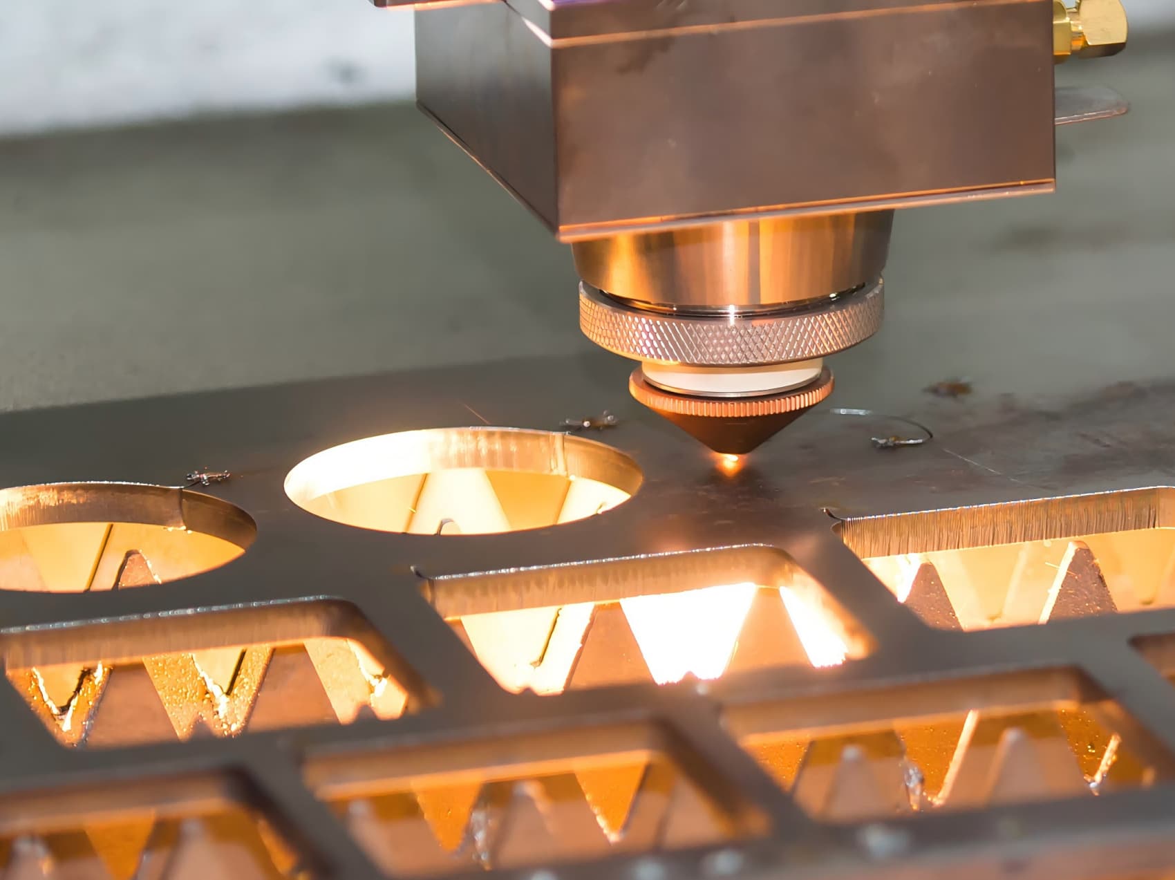
Short answer: motor lamination stamping produces thin silicon steel sheets that are stacked to form stator and rotor cores for electric motors. The critical RFQ factors are silicon steel grade, thickness, lamination profile tolerance, burr height, insulation coating, stacking method, and interlocking or welding requirements.
This guide is for motor design engineers, procurement teams, and EV powertrain buyers who need to specify stamped motor laminations, stator cores, rotor cores, and lamination stacks. Small differences in material grade, die clearance, burr control, and coating quality directly affect motor efficiency, torque ripple, and audible noise.
Send drawings with lamination profile, material grade, thickness, stacking height, and coating requirements through the RFQ form. For related high-precision stampings, see precision small ìtẹ irin for electronics and EV battery stamping parts and busbars.
Common motor lamination applications
- EV traction motor stators and rotors for passenger cars, buses, and trucks.
- Industrial servo motor and spindle motor cores for machine tools and robotics.
- Home appliance motor cores for washing machines, compressors, fans, and pumps.
- Power tool motor cores for drills, grinders, and circular saws.
- Generator and alternator cores for automotive, marine, and standby power.
- Small precision motor cores for medical devices, actuators, and aerospace.
For automotive-specific motor parts, see automotive stamped brackets manufacturing guide.
Silicon steel material selection
Motor laminations are almost exclusively made from grain-oriented or non-oriented electrical steel (silicon steel). The grade determines magnetic permeability, core loss, and saturating flux density.
| Grade | Core loss W/kg (1.5T, 50Hz) | Typical thickness | Application |
|---|---|---|---|
| M19 (0.35 mm) | 2.0 – 2.5 | 0.35 mm | Industrial motors, generators |
| M15 (0.35 mm) | 1.7 – 2.1 | 0.35 mm | High-efficiency industrial motors |
| M27 (0.47 mm) | 3.0 – 3.5 | 0.47 mm | Appliance motors, power tools |
| M43 (0.64 mm) | 4.0 – 5.0 | 0.64 mm | Low-cost general purpose motors |
| NO20 (0.20 mm) | 1.2 – 1.6 | 0.20 mm | EV traction motors, high-frequency |
| NO10 (0.10 mm) | 0.8 – 1.2 | 0.10 mm | High-speed EV motors, aerospace |
For more material guidance, see ìtẹ irin material selection guide.
Lamination tolerances and burr control
Lamination stamping tolerances are tighter than general stamping because the core stack geometry directly affects magnetic circuit performance. Key tolerances include:
- Profile tolerance: ±0.05 mm for precision tooling, ±0.08 mm for commercial tooling. Slot dimensions for winding insertion typically need ±0.03 mm.
- Burr height: 0.03 mm max for most motor laminations. Burr above 0.05 mm causes interlaminar short circuits, increasing eddy current losses and reducing motor efficiency.
- Concentricity between stator inner diameter and rotor outer diameter: ±0.05 mm typical, ±0.03 mm for high-efficiency designs.
- Stack height tolerance after stacking: ±0.15 mm for welded cores, ±0.10 mm for interlocked cores.
Burr control is especially critical for thin laminations under 0.35 mm. The punch-to-die clearance must be optimized for each material thickness and grade. For burr standards, see ìtẹ irin burr control guide.
Tooling for motor laminations
Motor laminations are typically produced in a irinṣẹ ìtẹ ìtẹ̀síwájú that combines blanking, piercing of slots and shaft holes, and notching in a single press stroke. High-volume production uses carbide or powder metallurgy steel dies for extended tool life between regrinds.
Key tooling considerations include:
- Die material: carbide for runs above 500,000 strokes between regrinds; D2 or DC53 tool steel for shorter runs or prototype quantities.
- Lamination separation: laminations are usually separated from the strip by a slight pushback or by a scrap skeleton that carries the strip through the die. For irinṣẹ ìtẹ ìtẹ̀síwájú tooling details, see irinṣẹ ìtẹ ìtẹ̀síwájú stamping cost breakdown.
- Notching vs full blanking: some dies notch the outer profile and slot geometry in multiple stations rather than blanking the full profile in one station, reducing press tonnage requirements.
For die maintenance guidance, see stamping die maintenance and tool life guide.
Stacking and core assembly
Individual laminations must be stacked and joined to form a rigid core. Common stacking methods include:
- Interlocking (dovetail or V-notch) — laminations lock together through pressed features. No separate fasteners needed. Most common for volume production.
- Laser welding — the stack OD or ID is welded at several points. Provides a strong joint but may cause small burrs on the weld bead that affect the air gap.
- Adhesive bonding — laminations are coated with a thermosetting adhesive before stacking. Minimizes interlaminar shorts but adds process cost.
- Through-bolt or clamp — used for larger cores where disassembly for rewinding may be needed.
- Clevis or rivet — mechanical fastening through stack holes.
Stacking method should be specified on the RFQ drawing. For assembly-related guidance, see stamped metal assemblies and secondary operations.
Insulation coating
Each lamination must be electrically insulated from its neighbors to minimize eddy current losses. Insulation coatings include:
- C0 — natural oxide layer, minimal insulation. Used only for very low-frequency or low-efficiency applications.
- C2 — inorganic phosphate coating. Good for most industrial motors up to 400 degrees C annealing temperature.
- C3 — organic-inorganic hybrid coating. Better punchability and insulation than C2. Most common for EV and high-efficiency motors.
- C4 — inorganic phosphate with higher insulation resistance for large generators.
- C5 — stress-relief anneal grade coating that withstands annealing temperatures above 800 degrees C.
The coating must survive the stamping process without chipping at the sheared edges. Pre-coated and post-stamp coating options should be discussed with the stamper. For plating and coating details, see ìtẹ irin plating and passivation RFQ guide.
RFQ checklist for motor laminations
- Drawing with lamination profile, slot geometry, shaft hole, keyway, and stacking features.
- Material: silicon steel grade, thickness, and coating type (C0-C5).
- Stacking method: interlock, weld, bond, or clamp. Specify interlock location and depth if applicable.
- Stack height and tolerance after final assembly.
- Burr height max and measurement method (typically optical or profilometer).
- Annual volume and order quantity per lamination design.
- Tooling: carbide or tool steel, and expected die maintenance schedule.
- Inspection: magnetic property test, dimensional check, stack height, burr audit.
- Packaging: trays with separator sheets to prevent lamination edge damage during transport.
Submit your lamination drawing through the RFQ form. For broader RFQ preparation, see the ìtẹ irin RFQ checklist.