
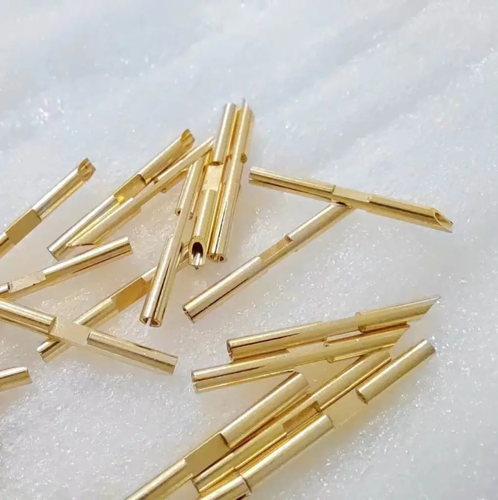
Short answer: Lead frame RFQs should define coplanarity, lead sweep, burr direction, plating, carrier strip support, cleanliness, and tray or reel handling before price is compared. The drawing should separate solderable areas, habarlaşmak areas, cut edges, and cosmetic limits, then state the inspection fixture, sample quantity, and whether measurements are taken before or after plating and packing.
A lead frame can be dimensionally close and still create assembly trouble if the leads are swept, the seating plane is unclear, or burrs point toward a solder or bonding surface. The RFQ should treat the lead frame as an assembly input, not only a flat stamped outline.
Use this page with the lead frame möhürleme guide, reel-to-reel möhürleme guide, coplanarity guide, and terminal plating thickness inspection guide.
Lead frame details to define before quoting
| Detail | Why it matters | RFQ evidence |
|---|---|---|
| Coplanarity plane | Different datums can make the same part pass or fail. | Seating plane, fixture support, probe points, and measurement condition. |
| Lead sweep | Thin leads can move during forming, plating, packing, or handling. | Lead width, pitch, tip location, allowed sweep, and sample stage. |
| Burr direction | Burrs can affect soldering, bonding, insertion, or plating coverage. | Functional edge map, maximum burr, and accepted cut-edge exposure. |
| Handling format | Carrier strip, trays, reels, and loose packing change deformation risk. | Carrier design, pocket support, stack height, and no-touch surfaces. |
Define the functional surfaces first
Lead frames often have several surfaces with different functions: solder tails, bond pads, habarlaşmak fingers, alignment holes, carrier bridges, dam bars, and trim edges. If those zones are not identified, the ü üpjün ediji may optimize the wrong feature. A burr that is harmless on a carrier bridge may be unacceptable on a solder tail or bond area.
The drawing should show which dimensions are checked in strip, after trim, after form, after plating, and after packing. If plating is applied after möhürleme, ask whether buildup changes coplanarity or lead spacing. If pre-plated strip is used, ask how exposed cut edges and forming strain are controlled.
Separate prototype evidence from production evidence
Prototype lead frames may be laser cut, wire cut, or stamped with simpler tooling. That can prove geometry, but it may not prove final strip feed, burr direction, plating coverage, or tray handling. For production, the quote should explain how pilot samples will be measured and what changes when the tool runs at normal speed.
If the lead frame goes into soldering, bonding, insert molding, or automated assembly, define the receiving evidence early. A good first article package may include dimensional data, photos of edge condition, plating thickness, coplanarity readings, cleanliness notes, and packed sample photos. For solderable areas, connect the plan to the solderability test guide; for residue-sensitive surfaces, use the cleanliness control guide.
RFQ details to include
- 2D drawing and model with solder zones, habarlaşmak zones, lead tips, carrier features, trim lines, and no-touch surfaces.
- Material derejesi, thickness, temper, grain direction if relevant, plating stack, underplate, and whether pre-plated strip is allowed.
- Coplanarity plane, lead sweep limit, pitch tolerance, burr direction, maximum burr, and inspection fixture rule.
- Amal stage for measurement: in strip, after trim, after forming, after plating, after cleaning, or after packing.
- Packaging format, tray pocket support, reel direction, ESD need, lot labeling, and shipment route.
- Prototype quantity, annual volume, first article report needs, and any current assembly reject history.
How to compare ü üpjün ediji answers
A strong ü üpjün ediji answer separates möhürleme risk, plating risk, and handling risk. It should ask about functional surfaces, seating plane, inspection stage, and whether the buyer has assembly data from the final process. A weak answer only says the part can be stamped.
Ask how the ü üpjün ediji will react if coplanarity passes before packing but fails at receiving. The answer should discuss fixture repeatability, tray support, shipment evidence, and whether the drawing needs a final-condition requirement.
Iberiň drawings, material, plating, lead sweep limits, coplanarity method, packaging needs, and sample quantity through the habarlaşmak page. If the process route is not fixed, use the RFQ form to compare pre-plated strip, post-plating, and trim-after-plate options before tooling is frozen.
FAQ
What is lead frame coplanarity?
It is the variation of lead or pad heights from a defined seating plane, usually checked with a fixture, optical system, or probe method that matches the assembly condition.
Why does burr direction matter on lead frames?
Burrs can interfere with soldering, bonding, insertion, plating coverage, or handling, so functional edges should have a defined burr side and maximum burr limit.
Should lead frames be measured before or after plating?
Use the stage that matches the final risk. Some dimensions are useful before plating, but final assembly features should often be checked after plating and packing.
What should be sent for a lead frame RFQ?
Iberiň drawings, material, plating, functional zones, coplanarity and lead sweep limits, burr requirements, packaging format, sample quantity, and inspection report needs.