
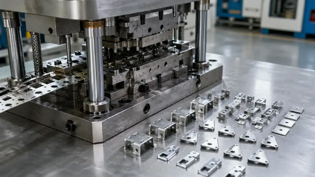
Short answer: Do not accept a transferred anwụ na-aga n’ihu because its footprint fits the press. Confirm shut height, bolster and bed interfaces, feed line, available tonnage through the working stroke, stroke and SPM assumptions, utilities, controls, sensors, die protection, scrap flow, lubrication, lifting, tool condition, strip history, sample evidence, and release criteria. Compatibility must be demonstrated in a controlled tryout; this site does not claim that any listed or proposed press will run an existing die.
A proven die can still misfeed, block scrap, trigger sensor faults, or form unstable parts in a different line. Start with the onye na-ebubata transfer checklist and tool ownership transfer guide, then evaluate the die as part of the proposed press system.
Build a press compatibility record before shipment
| Compatibility area | Evidence to compare | Acceptance question |
|---|---|---|
| Press geometry | Die envelope, shut height, stroke, bolster drawing, bed opening, clamps, and ram connection. | Can the die be installed, adjusted, supported, and serviced without improvised mounting? |
| Press capacity | Operation load by station, load location, press tonnage curve, energy data, and intended SPM. | Is capacity available where forming occurs, under the proposed running assumptions? |
| Feed and strip | Feed height, direction, pitch, stock width, coil set, straightener range, and strip layout. | Can stock enter, pilot, advance, and exit without changing the die’s intended progression? |
| Interfaces | Air, electrical connectors, valves, sensors, lubrication points, and protection logic. | Can every required function be connected and proven rather than bypassed? |
Check shut height, bolster, bed, and feed line
Record the die’s closed height under the condition used by the former setup sheet. Compare it with press adjustment, ram position, planned parallels, and working stroke. A shut-height value without its measurement condition can create a false match.
For the bolster and bed, compare the lower-die footprint, support zones, openings, mounting locations, clamp access, stock rails, and lower connections. The die should not bridge unsupported areas. Confirm whether scrap, slugs, and parts pass through the bolster or leave from the side.
Feed height and feed direction need a drawing showing entry, exit, pitch, pilot release, strip lift, coil centerline, and feeder clearance. Nyochaa the strip layout and carrier design guide when setup depends on carrier strength, pilot holes, or cutoff arrangement.
Validate tonnage through the stroke, not by nameplate alone
A press nameplate is not a compatibility approval. Compare the load profile with the tonnage curve at the working position. Include off-center loading, simultaneous stations, forming energy, reverse load where relevant, and each major event’s position above bottom dead center. The press tonnage capacity guide explains why rated and usable capacity differ.
Document the Nke gara aga stroke and SPM, but treat them as assumptions. Stroke changes affect feed time, sensor windows, stripper behavior, ejection, lubrication, and heat. SPM changes can expose problems hidden during hand cycling. Do not apply a universal safety margin or promise speed before testing the new line.
Map air, controls, sensors, and die protection
List every pneumatic function, documented pressure or flow requirement, connector, valve state, and loss-of-air behavior. Also record electrical voltage, pinout, grounding, encoder or cam signals, and communication with feeder and press controls.
Create an input-output list for pilots, stock buckle detection, end-of-stock, part-out, slug detection, misfeed, stripper position, cam return, and other in-die sensors. Define the expected state and stop response for each signal. The in-die sensor and error-proofing guide is useful when rebuilding the protection logic. Incoming acceptance should reject undocumented bypasses; a sensor that is present but not connected is not protection.
Plan scrap, lubrication, lifting, and die handling
Nyochaa scrap flow before setup. Confirm chute angles, bed openings, slug paths, conveyor position, carrier cutoff, bin access, and jam detection. Include the largest expected scrap shape, not only clean samples. A blocked chute can damage a healthy die.
Identify lubricant type, application points, delivery, material and downstream compatibility, containment, and cleaning. A change can affect forming, galling, sensor contamination, weldability, or finish. Record what the Nke gara aga ụlọ ọrụ used, not a generic oil description.
Verify die weight, center of gravity, lift points, fork pockets, transport locks, upper-to-lower retention, and storage supports. Compare them with crane, forklift, cart, bolster height, and aisle limits. Handling approval belongs in incoming acceptance, not after delivery.
Inspect die condition and preserve the production baseline
Inspect punches, die sections, pilots, guide posts, bushings, springs, cams, lifters, strippers, fasteners, heel blocks, wear plates, sensors, wiring, and visible repairs. Photograph condition before cleaning hides evidence. Nyochaa maintenance counts, sharpening history, broken-tool events, open deviations, spare inserts, and known recurring defects against the die maintenance and tool life guide.
The incoming package should include the controlled strip layout, setup sheet, last known acceptable strip, progressive station samples if available, finished samples, rejected samples that explain past issues, material certificates, dimensional reports, control plan, capability records, and inspection fixture details. Use the first article inspection checklist and incoming inspection checklist to separate tool acceptance from part acceptance.
Release production only after a controlled tryout
Define tryout gates before setup: receiving inspection complete, safe installation approved, dry cycle or hand cycle complete, sensors challenged, strip advanced at controlled speed, first-off parts inspected, scrap flow observed, lubricant confirmed, and an agreed sample quantity produced under recorded stroke and SPM conditions. The release record should name open issues, temporary controls, owners, due dates, and the person authorized to approve production.
Physical fit, a few good parts, or a Nke gara aga ụlọ ọrụ’s production history is not enough by itself. Use the tooling tryout and sample approval guide and control plan checklist to establish a documented handoff.
For a compatibility review, submit the die nameplate, overall envelope and mounting dimensions, shut height data, strip layout, approved samples, and the history of misfeeds, breakage, burr, dimensional drift, sensor faults, or other recurring problems through the kọntaktị page. Use the RFQ form to request an incoming die acceptance review. Provide the proposed press information as well; compatibility cannot be concluded from the die package alone.
FAQ
Does matching die footprint prove press compatibility?
No. Footprint is only one check. Shut height, support, feed line, tonnage through the stroke, controls, utilities, scrap flow, and safe handling must also be verified.
What records should arrive with a transferred anwụ na-aga n’ihu?
Request the nameplate data, drawings, strip layout, setup sheet, sensor list, maintenance history, spare list, accepted samples, problem samples, and inspection records.
Can the old ụlọ ọrụ’s SPM be used as the new production speed?
It can be a reference assumption, not an automatic release value. The new press, feed, lubrication, sensors, scrap system, and material behavior must be proven during tryout.
When should an incoming die be released for production?
Release it after installation safety, protection functions, controlled cycling, strip progression, part inspection, scrap handling, and documented open issues meet the agreed acceptance plan.